Whether positive or negative, your feedback helps us continually
improve the Tek.com experience. Let us know if you're having trouble or if we're
doing an outstanding job.
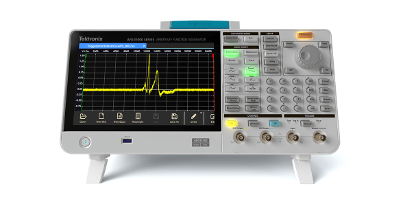
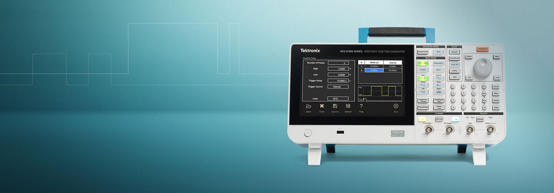
Today's designs are often complex, demanding a variety of stimulus signals during test. Tektronix
function generators are best-in-class instruments that deliver uncompromised frequency agility and
ensure signals are accurately reproduced every time.
With pre-loaded standard waveforms, arbitrary waveform capability, and signal impairment options,
Tektronix function generators support a wide range of applications and provide an economical
solution for applications that don’t require the advanced capabilities of an arbitrary waveform
generator.
Find the right arbitrary function generator for your application or explore all Tektronix signal generators.
You can only compare up to 3 products. To compare this
item, uncheck one of the other 3 products.
Please select at least two product series first.
×
How to choose an arbitrary function generator
Though there are a number of factors to consider when choosing the right arbitrary function generator for
your bench, here are a few of the most important considerations.
Consideration
Description
Sample rate
This affects the frequency and fidelity of the main output signal. The sampling
frequency must be more than twice that of the highest spectral frequency component of
the generated signal to ensure accurate signal reproduction.
Bandwidth
The analog bandwidth of a signal generator’s output circuitry must be sufficient to
handle the maximum frequency that its sample rate will support. In other words, there
must be enough bandwidth to pass the highest frequencies and transition times that can
be clocked out of the memory without degrading the signal characteristics.
Record length
This determines the maximum number of samples that can be stored and plays an important
role in signal fidelity because it determines how many points of data can be stored to
define a waveform. Particularly in the case of complex waveforms, memory depth is
critical to reproducing signal details accurately.
Output frequency range
Perhaps one of the most important considerations—and often the biggest driver of
price—is the frequency range. It’s essential to choose a function generator that can
operate in a frequency range that supports your tests.
Noise and jitter
These two characteristics are very closely related and are essentially undesired
distortions of the signal, which you want to keep as low as possible.
Number of channels
Depending on the application needs, a single output may be sufficient. But for IQ
modulation for instance, two outputs are mandatory.
User interface
A large, modern touchscreen with responsive feedback has become a key factor in labs
where test time is essential.
Arbitrary function generator FAQs
What is a function generator used for?
A function generator is a piece of electronic test instrument used to generate and deliver standard
waveforms, typically sine and square waves, to a device under test. It can be used to test a design or
confirm that a piece of electronic equipment is working as intended.
What’s the difference between a function generator and a signal generator?
A signal generator is any device that creates electronic signals. A vector signal generator specializes
in creating RF signals with analog and digital modulation schemes in formats such as QAM, QPSK, FSK,
BPSK, and OFDM.
A function generator is a specialized piece of test equipment that has a preset list of waveforms or
patterns that it can play. Function generators are known for their ability to rapidly switch from one
frequency to another and are a more economical option than other more advanced waveform generators.
How do function generators work?
A function generator connects to a device under test (DUT) via test leads and creates voltage waveforms
at a desired frequency to the DUT. Using the instrument’s front panel, the operator can change the
parameters of a waveform, such as how fast it’s played, the amplitude and offset, or add basic
distortion or modulation.
Whether positive or negative, your feedback helps us continually improve the
Tek.com experience. Let us know if you're having trouble or if we're doing an outstanding job.
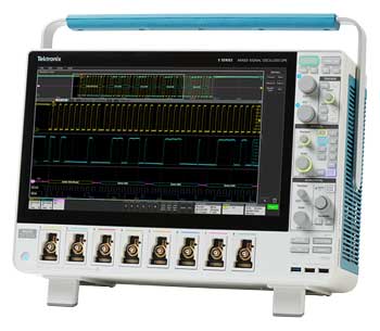
Bench Oscilloscopes for Design, Debug and Education
With new features and options added to our versatile portfolio, you'll find the right oscilloscope for
your education, embedded design and RF bench.
Lower noise and improved signal integrity
Bigger screens and improved user interface
Outstanding signal processing capability
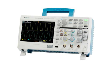
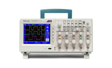
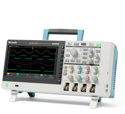
First Choice for Educators - All New TBS1000C
The new TBS1000C has a new user interface and refreshed look and feel that is intuitive and easy to
use. Built-in courseware features help both students and educators during labs.
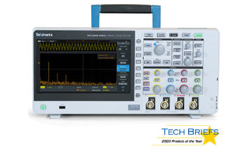
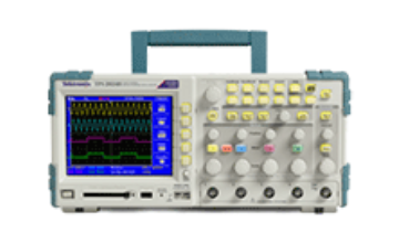
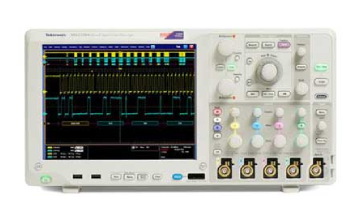
Troubleshoot and Debug Embedded Systems with the TBS2000B
The TBS2000B's large screen allows you to see more of your signals while the TekVPI™
probe interface enables you to use the latest generation active voltage and current probes in
addition to the standard BNC probes.
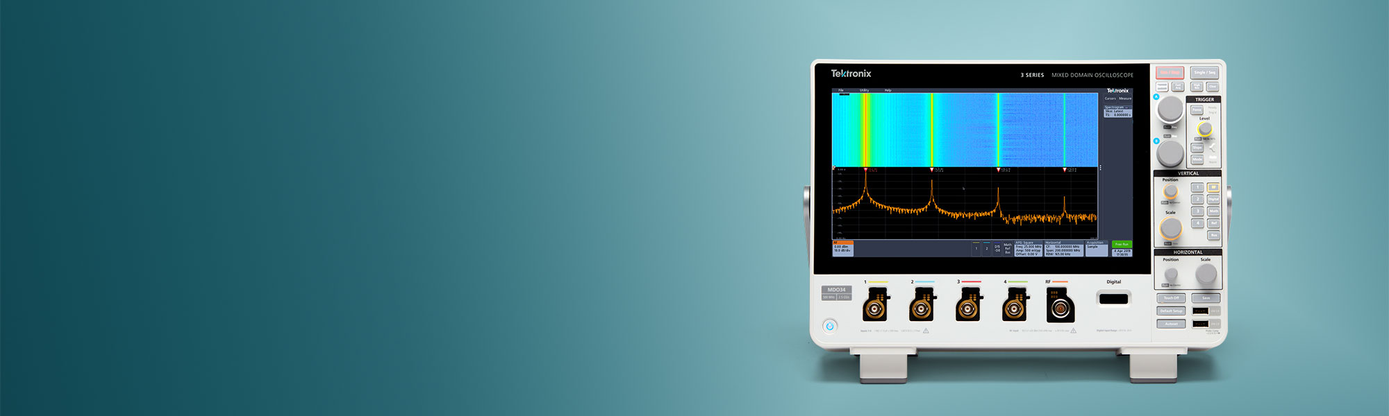
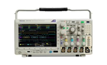
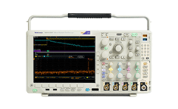
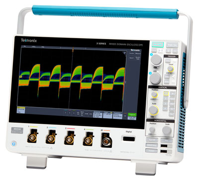
Measure Complex Embedded Systems, Serial Bus and RF with the 3 Series Mixed Domain Oscilloscope
With the largest display in class, improved low-level signal measurement accuracy, a built-in
spectrum analyzer, and industry-leading probe performance, the 3 Series MDO sets a new
standard for bench oscilloscopes.
A systems bandwidth determines a scope’s fundamental ability to measure an analog signal, the
maximum
frequency range that it can accurately measure. A bandwidth of 100MHz can accurately (within 2%) show the
amplitude of sine-wave signals up to 20MHz.
The right sample rate?
We’d recommend using a sample rate of 5x your circuit’s highest frequency component to ensure
you
get sufficient waveform detail.
The longer, the better
Time captured = record length/sample rate. So, with a record length of 1 Mpoints and a sample rate of 250
MS/sec, the oscilloscope will capture a signal 4 ms in length. A good basic scope will store over 2000
points,
which is more than enough for a stable sine-wave signal (which needs perhaps 500 points). But to find the
causes
of timing anomalies in a complex digital data stream you should consider an oscilloscope with a record
length of
1 Mpoints or more.
How many channels do you need?
The more time-correlated analog and digital channels your scope has, the more points in a circuit you can
measure at the same time and the easier it is to decode a wide parallel bus, for instance. Select the
amount of
channels to suit your application. 2 or 4 analog channels will allow you to view and compare signals
timings of
your waveforms, while debugging a digital system with parallel data needs an additional 8 or 16 digital
channels
and sometimes more.
Do you need mixed signal debugging?
Adds digital timing channels which indicate high or low states and can be displayed together as a bus
waveform.
Do you need advanced triggering?
All scopes provide edge triggering and most offer pulse width triggering. To acquire anomalies and make
best
use of the scope’s record length, look for a scope that offers advanced triggering on more
challenging
signals. The wider the range of trigger options available, the more versatile the scope and the faster you
get
to the root cause of the problem.
What is Wave Inspector® navigation?
Tek Wave Inspector® navigation controls provide easy navigation and automated search of
waveform
data
The more, the better.
Tools to automate the search process and accelerate your time to answer include zoom and pan, play and
pause,
markers and advanced search.
What is TekVPITM ?
TekVPI™ not only supports standard BNC probes, but also allows you to use latest-generation active
voltage and current probes. It provides wide application coverage and you don't have to worry about scale
factors.
What’s included?
HelpEverywhere provides helpful on-screen tips.
Built-in Scope Intro handbook provides operating instructions and oscilloscope fundamentals.
Dedicated tools for Educators
Courseware function presents lab exercise guidance on the display.
Fully compatible with TekSmartLab lab management software for education.
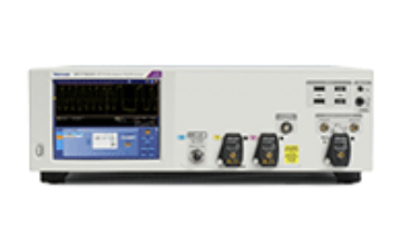
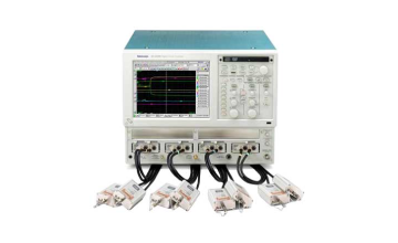
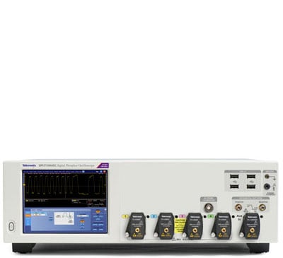
Engineers rely on an oscilloscope throughout their design cycle, from prototype turn-on to production
testing. The MSO/DPO70000 Series oscilloscopes unique capabilities combined with exceptional signal
acquisition performance and analysis accelerate your measurement tasks.
Key performance specifications
Up to 33 GHz analog bandwidth and rise time as fast as 9 ps. Enables measurement on the latest
high-speed serial standards
True 33 GHz Real-time Analog Bandwidth on 2 Channels with 33 GHz models
Industry-leading sample rate and timing resolution
100 GS/s on 2 Channels (33, 25, 23, 20, 16, and 12.5 GHz models)
Four-channel Simultaneous Performance
Up to 23 GHz Bandwidth
Up to 50 GS/s Real-time Sample Rate
Up to 500 Megasample Record Length with MultiView Zoom™ for quick navigation
Fastest Waveform Capture Rate with >300,000 wfms/s maximum per channel
16 Logic Channels with 80 ps Timing Resolution for Debug of digital and analog signals (MSO70000
Series only)
Unique iCapture® capability enables viewing analog characteristics of digital channels with single
probe connection
6.25 Gb/s Real-time Serial Trigger – Assures triggering on the first instance of a specified NRZ
or 8b/10b pattern to allow isolation of pattern-dependent effects
Application Support for High-speed Serial Industry Standards, wideband RF, Power supplies, and
memory – Enables standard-specific certification, measurement automation, and ease of use
Key features
Superior signal integrity and excellent signal-to-noise ratio – observe the truest representation
of your waveform
Pinpoint triggering – minimize time spent trying to acquire problem
signals for efficient troubleshooting and shortened debug time
Visual Trigger – precisely qualify triggers and find unique events in complex waveforms
Search and Mark – provides waveform or serial bus pattern matching and software triggers for
signals of interest
Automated Serial Analysis options for PCI Express, 8b/10b encoded serial data, I2C,
SPI, CAN, LIN, FlexRay, RS-232/422/485/UART, USB 2.0, HSIC, MIL-STD-1553B, and MIPI®
C-PHY, D-PHY and M-PHY
P7700, P7600, and P7500
TriMode probing system – perfectly matched signal connectivity, with
calibration to probe tip
P6780, P6750, and P6717A high-performance 17-channel logic probes with bandwidths up to 2.5 GHz
for connections to today's fast digital signals (MSO70000 Series only)
Connectivity
USB 2.0 host port on both the front panel and rear panel for quick and easy data storage,
printing, and connecting a USB keyboard
Integrated 10/100 Ethernet port for network connection and Video Out port to export the
oscilloscope display to a monitor or projector
DPO/DSA/MSO70000 Quick Selection Guide
Quick selection guide
Model
Analog Bandwidth
Analog Sample Rate – 2/4 Channels
Standard Memory – Analog + Digital
Analog Channels
Logic Channels
DPO70804C
8 GHz
25 GS/s
31 MS
4
—
MSO70804C
8 GHz
25 GS/s
62 MS
4
16
DPO71254C
12.5 GHz
100 GS/s / 50 GS/s
31 MS
4
—
MSO71254C
12.5 GHz
100 GS/s / 50 GS/s
62 MS
4
16
DPO71604C
16 GHz
100 GS/s / 50 GS/s
31 MS
4
—
MSO71604C
16 GHz
100 GS/s / 50 GS/s
62 MS
4
16
DPO72004C
20 GHz
100 GS/s / 50 GS/s
31 MS
4
—
MSO72004C
20 GHz
100 GS/s / 50 GS/s
62 MS
4
16
DPO72304DX
23 GHz
100 GS/s / 50 GS/s
31 MS
4
—
MSO72304DX
23 GHz
100 GS/s / 50 GS/s
62 MS
4
16
DPO72504DX
25 GHz
100 GS/s / 50 GS/s
31 MS
4
—
MSO72504DX
25 GHz
100 GS/s / 50 GS/s
62 MS
4
16
DPO73304DX
33 GHz
100 GS/s / 50 GS/s
31 MS
4
—
MSO73304DX
33 GHz
100 GS/s / 50 GS/s
62 MS
4
16
Application support
High-speed serial industry standards compliance
SignalVu RF and vector signal analysis
DDR memory bus analysis
Applications
Design verification including signal integrity, jitter, and timing analysis
Design characterization for high-speed, sophisticated designs
Certification testing of serial data streams for industry standards
Memory bus analysis and debug
Prototype turn-on and power supply verification
Research and investigation of transient phenomena
Production testing of complex systems
Spectral analysis of transient or wide-bandwidth RF signals
System turn-on and verification
From the time a design is first powered up through the initial operational checks, the MSO/DPO70000
Series provide the features you need.
Uncompromised four-channel acquisition
With very low noise and up to 50 GS/s sample rate on all four channels the DPO70000 Series ensures that
signal integrity checks and timing analysis can be done without worrying about noise and jitter in the
scope distorting the measurements. Single-shot bandwidths up to 23 GHz on all four channels ensure that
you'll capture your signals of interest without worrying about undersampling when using more than 1 or 2
channels.
For applications requiring the lowest internal noise and jitter, 100 GS/s performance further reduces
noise and jitter and provides additional measurement headroom.
Unmatched acquisition and signal-to-noise performance
The superior signal integrity and excellent signal-to-noise ratio of the MSO/DPO70000 Series ensures
confidence in your measurement results.
Up to 33 GHz, matched across 4 channels
Bandwidth enhancement eliminates imperfections in frequency response all the way to the probe tip.
User-selectable filters for each channel provide magnitude and phase correction for more accurate
representation of extremely fast signals. In addition, only Tektronix allows the user to disable the
bandwidth enhancement for applications needing the highest measurement throughput.
Simultaneous high sample rate on all channels captures more signal details (transients,
imperfections, fast edges)
100 GS/s on 2 channels and 50 GS/s on all analog channels for the 12.5 through 33 GHz models
25 GS/s on all analog channels for the 8 GHz models
12.5 GS/s on all logic channels in the MSO70000 Series
Low jitter noise floor and high vertical accuracy provide additional margin in your measurements
Long record length provides high resolution and extended-duration waveform capture
Standard 31 MS per channel on the DPO70000 Series and 62 MS on the MSO70000 Series
Optional up to 125 MS on all four channels (8 GHz models) and 250 MS (12.5 through 20 GHz
models) on all four channels; up to 500 MS on four channels/1 GS on two channels for 23, 25, and
33 GHz models.
On the MSO70000 Series, the record length of logic channels matches the analog record lengths
for uncompromised analog and digital acquisition
MultiView Zoom helps you manage long records, compare and analyze multiple waveform segments
With high signal-to-noise ratio and low internal noise floor, the MSO/DPO70000 Series enable you to
perform precise characterization measurements. When debugging a DUT, a low noise floor and maximum
signal fidelity of the measurement instrument allows you to find the smallest anomalies affecting
the DUT's performance. For RF signals, a lower noise floor translates into a higher dynamic range,
opening the MSO/DPO70000 Series to a wider range of applications.
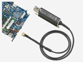
Widest range of probing solutions
Whether you need to measure 8 Gb/s serial data, fast digital logic, or switching currents from your new
power supply design, Tektronix offers a vast array of probing solutions, including active single-ended,
differential, logic, high voltage, current, optical, and a wide range of probe and oscilloscope
accessories.
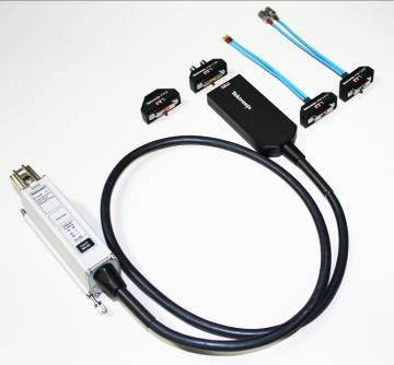
P7633 Low Noise TriMode probes simplify complex measurement setups.P6780 Differential Logic probes provide high-bandwidth connections for up to 16 digital
signals.
16-channel digital acquisition (MSO70000 Series)
When you have many interfaces to verify, the MSO70000 Series with 4 analog and 16 logic channels
enables efficient channel-to-channel timing checks. With timing resolution of 80 ps, the MSO70000 Series
digital acquisition system enables you to make precise timing measurements on as many as 20 channels
simultaneously.
iCapture™ – One connection for analog and digital (MSO70000 Series)
The number of signals that must be verified can often make the checkout of a design long and involved.
By using the iCapture digital-to-analog multiplexer feature, you can easily
verify the analog characteristics of any of the 16 signals connected to the MSO70000 Series digital
channels without changing probes or connections. Using iCapture, you can quickly
view the analog characteristics of any input channel. If the signal is working as expected, relegate it
to a digital-only view and continue testing other lines.
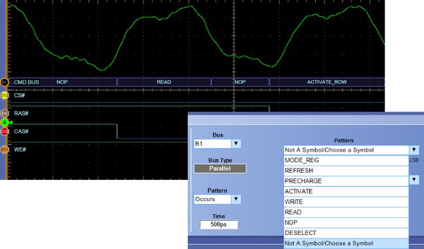
Bus decoding and triggering
Verifying your system operation often requires the ability to see specific system states on a key bus
such as the DDR SDRAM interface. The MSO/DPO70000 Series includes parallel and serial bus decoding that
provides deeper insight into the system's behavior. Using the bus triggering capability of the
MSO/DPO70000 Series to isolate the exact state needed or find invalid bus sequences is as easy as
defining the bus and choosing the bit pattern or symbolic word that describes the desired state. In
addition, serial bus decoding for 8b/10b encoded data, I2C, SPI, RS-232/422/485/UART, USB,
and
MIPI DSI and CSI2 buses enables you to identify where control and data packets
begin and end as well as identify subpacket components such as address, data, CRC, etc.
Symbolic bus formats simplify identifying system states and setting up bus triggers.
Deep record length available on all channels
Longer duration events such as power supply sequencing and system status words can be analyzed without
sacrificing timing resolution using the long memory depths available on all four analog channels in the
DPO70000 Series as well as the 16 logic channels of the MSO70000 Series. Optional memory depths up to
125 MS (Option 10XL) on the 8 GHz models, 250 MS (Option 20XL) on the 12.5 through 20 GHz models and 500
MS (4 channels)/1 GS (2 channels) with option 50XL on the 23 through 33 GHz models are available.
10 ms duration capture of synchronous high-speed and low-speed signals at 25 GS/s.
Power supplies can be a critical failure point in any system. Careful testing of the power delivery
system's power on sequence can be time consuming. The MSO70000 Series provides independent logic
thresholds for each logic channel enabling multiple logic voltages to be set up and observed
simultaneously for quick verification of the system's power rails.
Protocol and serial pattern triggering
To verify serial architectures, the serial pattern triggering for NRZ serial data streams with built-in
clock recovery in the MSO/DPO70000 Series allows correlating events across physical and link layers. The
instruments can recover the clock signal, identify transitions, and allow you to set the desired encoded
words for the serial pattern trigger to capture. This feature comes standard on the MSO70000 Series and
is available on the DPO70000 Series as Option ST6G. For higher bit rate standards like USB 3.0, the
8b/10b serial pattern trigger and decode covers data rates up to 6.25 Gb/s.
Pattern lock triggering adds an extra dimension to NRZ serial pattern triggering by enabling the
oscilloscope to take synchronized acquisitions of a long serial test pattern with outstanding time base
accuracy. Pattern lock triggering can be used to remove random jitter from long serial data patterns.
Effects of specific bit transitions can be investigated, and averaging can be used with mask testing.
Pattern lock triggering supports up to 6.25 Gb/s NRZ serial data streams and is standard on the MSO70000
Series instruments, or is included as part of Option ST6G on the DPO70000 Series.
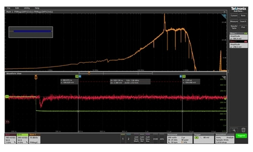
Visual Trigger – Find the signal of interest quickly
Finding the right cycle of a complex bus can require hours of collecting and sorting through thousands
of acquisitions for an event of interest. Defining a trigger that isolates the desired event speeds up
debug and analysis efforts.
Visual Trigger qualifies the Tektronix Pinpoint Triggers by scanning through all waveform acquisitions
and comparing them to on-screen areas (geometric shapes). Up to eight areas can be created using a mouse
or touchscreen, and a variety of shapes (triangles, rectangles, hexagons, or trapezoids) can be used to
specify the desired trigger behavior. Once shapes are created, they can be edited interactively to
create ideal trigger conditions
Visual Trigger extends the Tektronix oscilloscope's triggering capabilities for a wide variety of
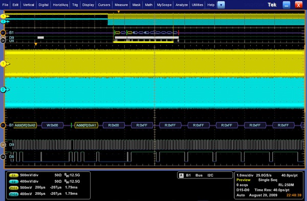
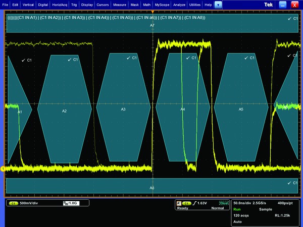
complex signals as illustrated by the examples shown here.
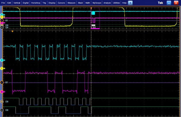
Customized serial triggering. Visual Trigger set to find a serial data pattern of 1101 0101.
Multiple channel triggering. Visual Trigger areas can be associated with events spanning
multiple channels such as packets transmitted on two USB2.0 buses simultaneously.
By triggering only on the most important signal events, Visual Trigger can save hours of capturing and
manually searching through acquisitions. In seconds or minutes, you can find the critical events and
complete your debug and analysis efforts. Using the Mark All Trigger Events feature, once your Visual
Trigger is set, your oscilloscope can automatically search the entire acquired waveform for all events
with the same characteristics and mark them for you - a great time-saving feature.
DDR memory bus events involve clocks, strobes and data channels as well as multiple amplitudes and
bursts of data.
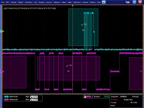
DDR memory. Visual Trigger used to isolate a rare occurrence of a write burst on a specific
bit pattern in DDR3. The trigger event is a Write DQ burst of 11000000, when the DQ launch starts from
a non-tri-state voltage value. DDR memory bus events involve clocks, strobes and data channels as well
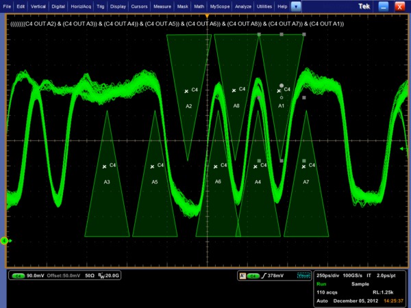
as multiple amplitudes and bursts of data.Boolean logic trigger qualification. Boolean logic using logical OR allows the user to
simultaneously monitor each bit and capture the occurrence of an anomaly at any point in the
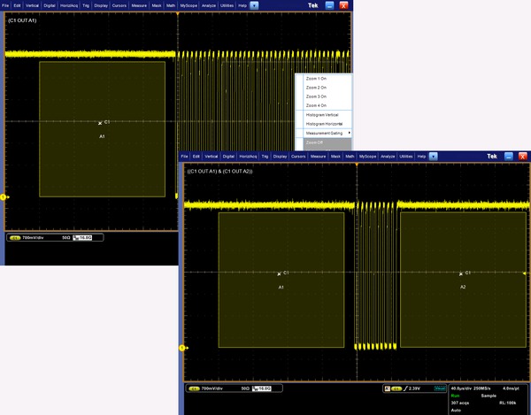
acquisition.Trigger on the width of a burst of 10 pulses. By drawing a "Must be outside" area before the
first clock pulse and a second "Must be outside" area after the tenth pulse, as shown, you can define
a Visual Trigger setup that captures the desired burst width.
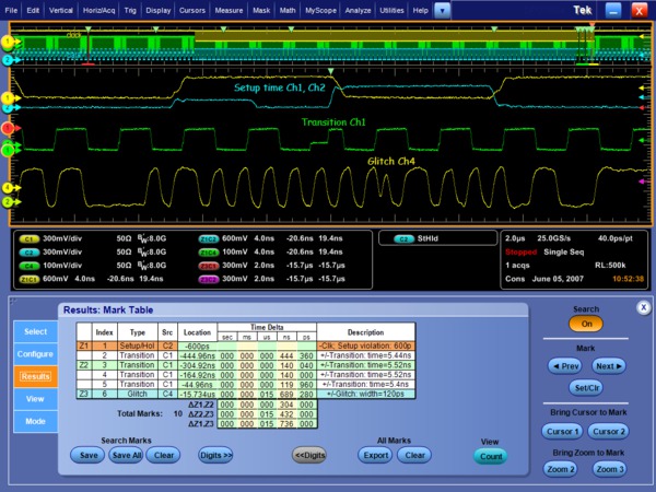
System characterization and margin testing
When a design is working correctly and the next task is to fully characterize its performance, the
MSO/DPO70000 Series offers the industry's most comprehensive set of analysis and certification tools,
such as math expressions, waveform mask testing, pass/fail testing, event searching, and event marking.
Tools for automation reduce the tedium, increase reliability, and speed up the process of making
hundreds of characterization measurements.
Advanced waveform analysis
Full analysis of the power, voltage, and temperature corners of your system under test can be very time
consuming. The MSO/DPO70000 Series offer a wide range of built-in advanced waveform analysis tools.
Waveform cursors make it easy to measure trace-to-trace timing characteristics, while cursors that link
between YT and XY display modes make it easy to investigate phase relationships and Safe Operating Area
violations. Select from 53 automatic measurements using a graphical palette that logically organizes
measurements into Amplitude, Time, Histogram, and Communications categories. Gather further insight into
your measurement results with statistical data such as mean, min, max, standard deviation, and
population.
Define and apply math expressions to waveform data for on-screen results in terms that you can use.
Access common waveform math functions with the touch of a button. Or, for advanced applications, create
algebraic expressions consisting of live waveforms, reference waveforms, math functions, measurement
values, scalars, and user-adjustable variables with an easy-to-use calculator-style editor.
With deep acquisition memory, margin testing can be done over many cycles and long duration trends in
the data can be observed. Plus, data from the oscilloscope can be captured into Microsoft Excel using
the unique Excel toolbar, and formatted into custom reports using the Word toolbar provided with the
MSO/DPO70000 Series.
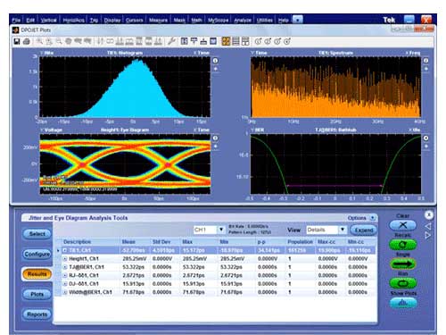
Automated tools to increase measurement throughput
Ease of use and measurement throughput are key when a large number of measurements must be completed
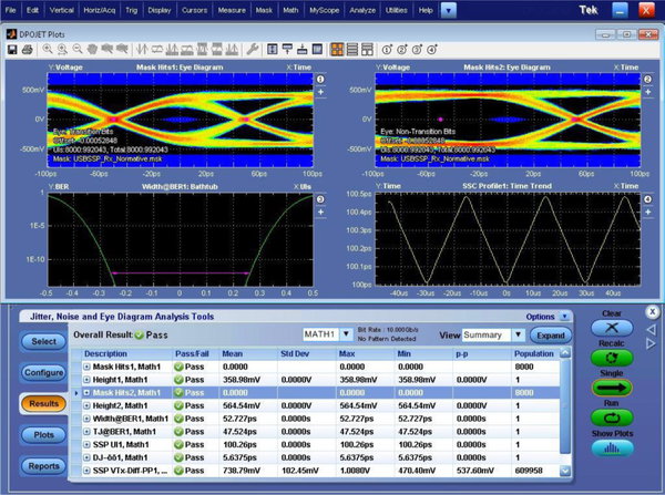
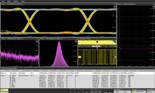
with a performance oscilloscope. MSO70000 Series come standard with the DPOJET Advanced Jitter and Eye
Diagram measurement application, providing the tools you need to quickly perform a high volume of
measurements and collect statistics. DPOJET Essentials is standard on the DPO70000 Series with the
DPOJET advanced version available as an option. Application-specific measurement packages are also
available that extend DPOJET and perform the extensive set of tests required by industry standard
groups. User-defined measurements can be added to DPOJET using the Application Developers Kit (ADK) that
comes standard with the oscilloscope.
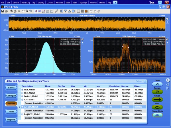
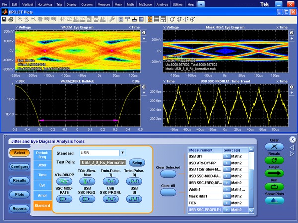
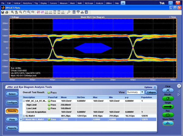
DPOJET Jitter and Eye Diagram Analysis – Simplify identifying signal integrity concerns,
jitter, and their related sources with DPOJET software. DPOJET provides the highest sensitivity and
accuracy available for real-time oscilloscopes.
To support the DPO7OE1 optical probe, DPOJET now also provides optical measurements, such as
Extinction Ratio (ER), Average Optical Power (AOP), Optical Modulation Amplitude (OMA), Optical High
value, and Optical Low value.
Error detector
When performing receiver testing on a serial transceiver, a BER measurement is often required. The
MSO/DPO70000 series offer an optional built-in error detector function for 8b/10b-encoded signals. The
built-in error detector comes with presets for testing PCIe, USB3.0, and SATA signals up to 6 Gb/s. The
error detector settings can be customized to work with a generic 8b/10b-encoded signal and can be set to
detect bit, character, or frame errors. When an error is detected, the scope will trigger and display
the waveform bits where the error occurred.
RF and vector signal analysis
When vector signal analysis of RF or baseband signals is needed, the optional
SignalVu application enables measurements in multiple domains (frequency, time,
phase, modulation) simultaneously.
SignalVu measurements are fully correlated with the scope's time domain
acquisition and triggering. Time domain events, such as commands to an RF subsystem, can be used as
trigger events, while the subsystem's RF signal can be seen in the frequency domain. SignalVu also
provides wireless standards measurements such as IEEE 802.11 a/b/g/j/p/n/ac that can be correlated in
the time domain
1.
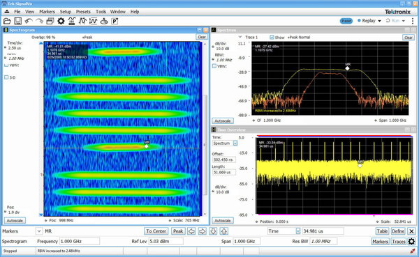
SignalVu® Vector Signal Analysis – Easily verify wide-bandwidth designs such as wideband
radar, high data-rate satellite links, WLAN 802.11, or frequency-hopping radios and characterize
wideband spectral events. SignalVu® combines the functionality of a vector signal analyzer, a spectrum
analyzer, and the powerful triggering capabilities of the MSO/DPO70000 Series – all in a single
package.
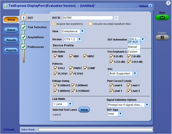
TekExpress® software automation framework
The
TekExpress software automation framework has been developed for automated
one-button testing of high-speed serial data standards.
TekExpress efficiently executes the required tests for many serial standards
such as SATA, SAS,
MIPI C-PHY,
MIPI D-PHY, MHL,
MIPI M-PHY,
PCI Express, USB 3.0, DisplayPort, and 10GBASE-T Ethernet. Run on an external
Windows PC, the
TekExpress software orchestrates the instrument setup and control sequences to
provide complete test results for complete design validation.
Beyond using the
TekExpress framework, custom applications that you develop yourself using
application development environments such as
MATLAB can further extend the tool set of the MSO/DPO70000 Series.
Characterization measurements depend upon accuracy and repeatability. The wide bandwidth and unmatched
signal fidelity of the MSO/DPO70000 analog front end ensures that your signal quality measurements such
as rise times are faithful and amplitude correct with flatness of ±0.5 dB.
TekExpress® USB 3.0 Automated Test Software (Option USB-TX) –TekExpress® USB 3.0 provides an
automated, simple, and efficient way to test USB 3.0 transmitter and receiver hosts and devices
consistent with the requirements of the SuperSpeed Universal Serial Bus Electrical Compliance Test
Specification. The application automates selection of appropriate fixture de-embed, CTLE and reference
channel emulation filters and measurement selections based on device type, test type, test points, and
selected probes. In addition, USB-TX leverages DPOJET allowing debug and advanced characterization of
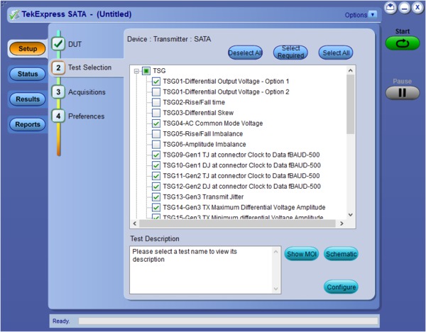
USB 3.0 solutions.TekExpress® SATA Automated Compliance Test Software – Complete support for SATA Gen1/2/3
defined test suites for transmitters and receivers. Reduce your compliance test time by approximately
70% with simple, efficient automation of all required test suites with TekExpress® software. Also
included is auto-recognition of all required test equipment, precise DUT/Host control, and one-button
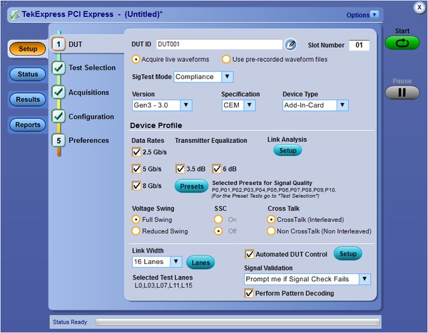
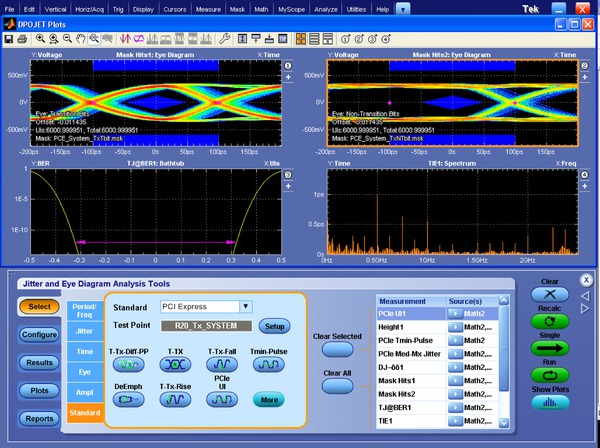
testing.TekExpress® PCI Express Gen 1/2/3 Automated Test Software (Option PCE3) - Provides the most
comprehensive solution for PCI Express Gen 1/2/3 transmitter compliance testing as well as debug and
validation of PCI Express devices against the PCI-SIG specifications. The application automates
selection of appropriate fixture de-embed and reference channel emulation filters and measurement
selections based on test type, device data rate, transmitter equalization, link width, and selected
probes. In addition, the Option PCE3 application includes a TekExpress compliance automation solution
that integrates the PCI-SIG's Sigtest test software with Tektronix DPOJET-based PCI Express Jitter and
Eye Diagram & SDLA Serial Data Link Analysis Visualizer analysis tools for debug. Results are
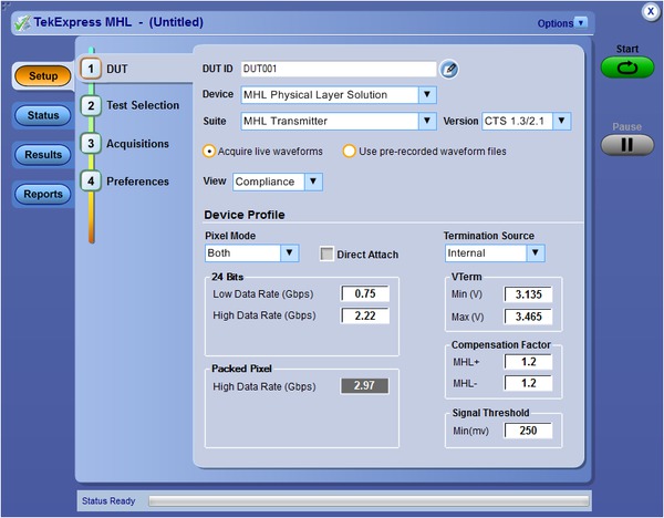
presented in a comprehensive HTML format for engineering test documentation.TekExpress® MHL Advanced Analysis and Compliance Software (Option MHD) - Provides the most
comprehensive solution for MHL 1.0/2.0/1.3/2.1 compliance testing as well as debug and validation of
MHL devices against the latest MHL specifications. The application automates Transmitter, Sink and
Dongle Electrical tests. Results are presented in a comprehensive HTML format for engineering test
documentation
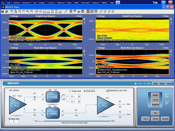
Custom filter and de-embed capability
Create your own filters or use the filters provided as standard with the MSO/DPO70000 Series to enhance
your ability to isolate or remove a component of your signal (noise or specific harmonics of the
signal). These customizable FIR filters can be used to implement signal-processing techniques, such as
removing signal pre-emphasis or minimizing the effects of fixtures and cables connected to the device
under test. Using the optional Serial Data Link Analysis Visualizer (SDLA64) application, you can gain
further insight into serial data links with the capability to emulate the serial data channel from its
S-parameters, remove reflections, cross-coupling, and loss caused by fixtures, cables, or probes, and
open closed eyes caused by channel effects using receiver equalization techniques, such as CTLE, DFE,
FFE. IBIS-AMI models for silicon-specific receiver equalization can be used to observe on-chip behavior.
SDLA - Serial Data Link Analysis Visualizer (Option SDLA64) – Offers the capability to
emulate the serial data channel, de-embed fixtures, cables, or probes, and add or remove equalization.
Option SDLA64 also provides processing of waveforms with IBIS-AMI Receiver Equalization, or CTLE, FFE
and/or DFE equalization. DPOJET provides advanced measurement and jitter analysis of the resulting
waveforms.
Application-specific solutions – enable standard-specific certification, measurement automation, and
extended signal analysis
Accurate, Simple, and Customizable Physical Layer Certification Testing – For designers with
industry-standard certification needs, standard-specific compliance and analysis modules that configure
the pass/fail waveform mask and measurement limit testing are available as options on the MSO/DPO70000
Series. Modules are available for PCI Express, DDR Memory, Serial ATA, SAS,
HDMI, Ethernet, DisplayPort, MIPI® C-PHY, MIPI® D-PHY and M-PHY, Power Supplies,
and USB.
See the following list for highlights of the available application-specific solutions:
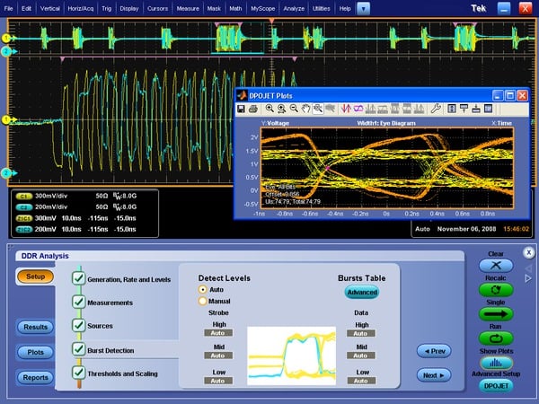
DDR Memory Bus Analysis (Option DDRA) – Automatically identify DDR1, LPDDR, LPDDR2, LPDDR3,
DDR2, DDR3, DDR4, and GDDR3 Reads and Writes and makes JEDEC conformance measurements with pass/fail
results on all edges in every Read and Write burst. DDRA provides capabilities for measurements of
clock, address, and control signals. In addition to enabling conformance testing DDRA with DPOJET is
the fastest way to debug complex memory signaling issues. DDRA can also use the Command/Address lines
to trigger on specific read/write states when running on the MSO70000 Series Mixed Signal
Oscilloscope, which offers 16 channels of digital logic probing.USB 3.0 Transmitter Test Solution (Option USB3) – Perform verification, characterization,
and debug of USB 3.0 devices. Measurements are implemented in DPOJET and are compliant to the USB 3.0
specification. For compliance and automation, USB-TX is available.PCI Express® Transmitter Compliance and Debug (Option PCE3) – Analyze the performance of
your PCI Express® Rev 1.0, 2.0, or 3.0 (draft spec) design with comprehensive test support. Using
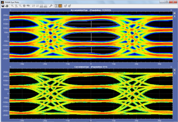
DPOJET, Option PCE3 enables tests that conform to PCI-SIG standards.NRZ and PAM4 measurements-The throughput of Datacom networks continues to increase. Tek's
DPO73304DX supports up to 10GBASE-KRn data rates. The powerful combination of the DPO70000, DPOJET
Jitter and Noise Analysis, and the SDLA Serial Data Link Analysis tool performs accurate de-embedding
and eye diagram analysis for Datacom standards.
For more information on PAM4 testing, please refer to the DPO70000SX datasheet and related PAM4
documents.
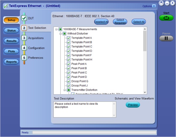
TekExpress Ethernet (Option CMENET3) – Receive full PHY layer support for Ethernet variants
10BASE-T, 100BASE-TX, and 1000BASE-T with the comprehensive, integrated Tektronix® TekExpress Ethernet
tool set. Analog verification, automated compliance software, and device characterization solutions
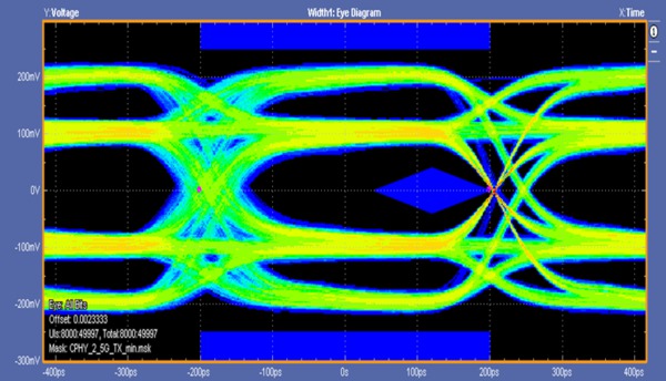
are all included.C-PHY uses a unique mechanism for clock recovery. C-PHY 1.0 implements a custom clock
recovery algorithm referred to as triggered eye. In this model, the first zero crossing of the four
differential signals is used as a trigger point for clock recovery and rendering the eye diagram. The
eye mask is optimally placed for maximum eye opening where the eye height is measured. Because of the
triggered eye mechanism, all the jitter at the trigger point (zero crossing) is swallowed and
reflected on the other side. Jitter and eye diagram rendering performed over the entire record length
helps designers better characterize devices by displaying anomalies of the device over an extended
period. The software allows you to run the eye diagram analysis for 3M UI and overnight runs for a
detailed characterization.MIPI® D-PHY Characterization and Analysis Solution (Option D-PHY) – Verify to the D-PHY
specification by rapidly characterizing and discovering sources of jitter and signal integrity
concerns using the fully flexible and customizable test setup. Using DPOJET, Option D-PHY enables
transmitter high-speed data-clock timing measurements, along with a full range of electrical
characteristics in high-speed or low-power modes.MIPI® M-PHY Debug, Analysis, Characterization and Conformance Test Solution (Option M-PHY) –
Verify to the M-PHY specification by rapidly characterizing and discovering sources of jitter and
signal integrity concerns. Using DPOJET, Option M-PHY enables transmitter signaling and timing
measurements such as differential transmit eye diagrams, rise and fall times, slew rate, amplitude
parameters, common mode voltages on each lane for both the large and small amplitude configurations,
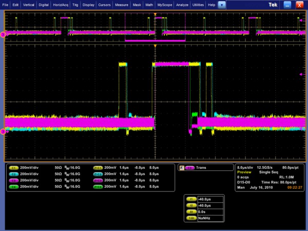
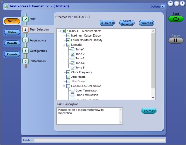
as well as the terminated and unterminated cases.TekExpress Ethernet Tx (Option XGBT2) – Quickly perform 10GBASE-T measurements per the IEEE
802.3an-2006 standard including Power Spectral Density (PSD), Power Level, and Linearity, with a
simplified instrument configuration. XGBT2 provides flexible control over test configurations and
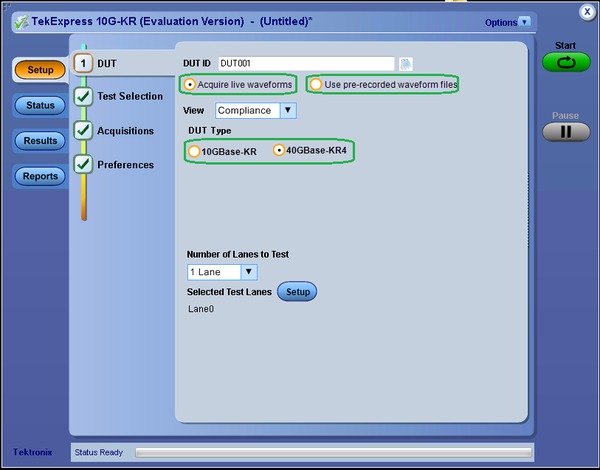
analysis parameters, enabling more in-depth device characterization.10GBASE-KR/KR4 Compliance and Debug Solution (Option 10G-KR) - Automated compliance
measurements for IEEE 802.3ap-2007 specifications. This option includes an automated compliance
solution and debugging with DPOJET. The automated test setup measures transmitter equalization levels
generating 12 results for each tap and 120 results for 9 different measurements in approximately 15
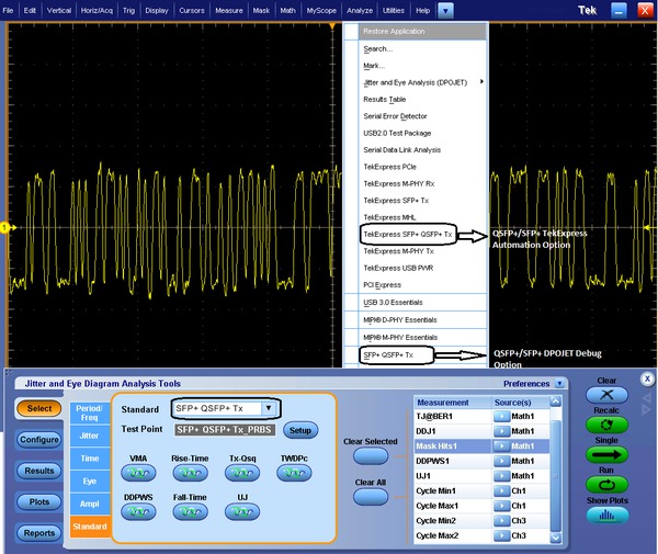
minutes.Tektronix SFP+ QSFP+ Tx is developed on a Real Time Oscilloscope platform, which is the
platform of choice for engineers designing their products around SFF-8431 & SFF-8634 technology.
Option SFP-TX and SFP-WDP enable both an Automation Solution (for Compliance) and DPOJET Option (for
Debug), Users can save up to 80% on testing time compared to manual testing. TWDPc - Transmitter
Waveform Distortion Penalty for Copper Measurements are available with Option SFP-WDP. SFF-8431 SFP+
TWDPc based MATLAB code is integrated into the SFP-WDP option to make sure Engineers can use this
measurement in the automated setup.HDMI Compliance Test Solution (Option HT3) – A fast, efficient solution for HDMI compliance
measurement challenges, no matter if you are working on a Source, Cable, or Sink solution. This
application provides all the HDMI compliance test solutions you need to ensure quality and
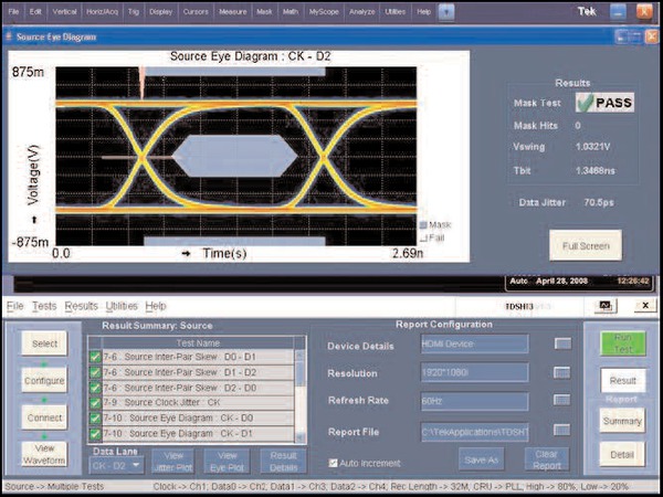
interoperability.DisplayPort Compliance Test Solution (Option DP12) – Supports DisplayPort Compliance Test
Standard (CTS) source test with four-line simultaneous testing using the Tektronix® P7300SMA Series
probes and DisplayPort software. Detailed test reports with waveform plots, pass/fail results, and
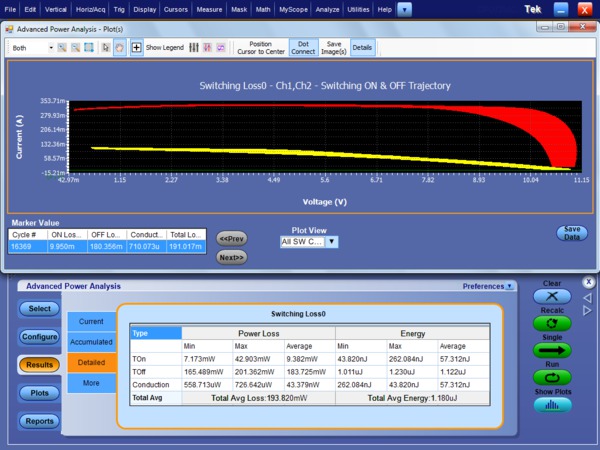
margin analysis are included.Power Measurement and Analysis Software (Option PWR) – DPOPWR, Advanced Power Measurement
and Analysis software allows the user to configure multiple measurements with custom defined settings,
measure and analyze power dissipation in switching devices, and magnetic parameters in a single
acquisition. The Trajectory plot computes turn-on loss, turn-off loss and Conduction loss parameters
for each cycle. Measurements such as Phase, Conduction loss, amplitude, and Voltage harmonics provide
more insight to Input/Output characterization of power supplies. A single mht format file with append
feature provides an easy way of generating reports which include measurements, test results, and plot
images.
Certification
This is the start of your concept. Before a product can go to market, you often need to complete a
series of certification tests on the industry-standard high-speed serial buses in your design. These
tests can involve many hours of wrestling with test fixtures, reading certification documents, and
collecting sufficient data to validate that your system passes the required tests.
MSO70000 – A dedicated solution configured for today's high-speed serial design challenges
The MSO70000 Mixed Signal Oscilloscopes are specially configured to address high-speed serial data
designs by encapsulating many of the serial domain features needed for high-speed serial verification
and characterization. These standard features on the MSO70000 Series are options on the DPO70000 Series.
Serial pattern triggering
Real-time serial pattern triggering and protocol decode with built-in clock recovery recovers the clock
signal, identifies the transitions, and decodes characters and other protocol data. You can see the
8b/10b bit sequences decoded into their words for convenient analysis, and set the desired encoded words
for the serial pattern trigger to capture. With pattern lock triggering, the MSO70000 Series can
synchronize to long serial test patterns with data rates up to 6.25 Gb/s and remove random jitter.
DPOJET jitter, timing, and eye diagram analysis
The MSO70000 Series features the highest-accuracy jitter and timing measurements as well as
comprehensive analysis algorithms. Tight timing margins demand stable, low-jitter designs. You can make
jitter measurements over contiguous clock cycles on every valid pulse in a single-shot acquisition.
Multiple measurements and trend plots quickly show system timing under variable conditions, including
Random, Deterministic, and Bounded Uncorrelated Jitter separation.
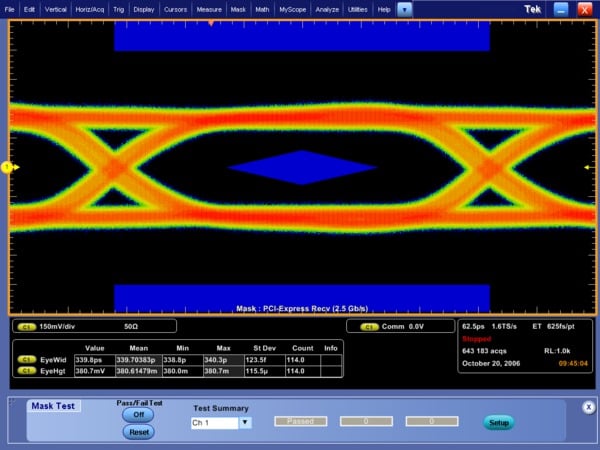
Communications mask testing
Provides a complete portfolio of masks for verifying compliance to serial communications standards.
Over 150 masks including the following standards are supported –
PCI Express, ITU-T/ANSI T1.102, Ethernet IEEE 802.3, ANSI X3.263, Sonet/SDH,
Fibre Channel, InfiniBand, USB, Serial ATA, Serial Attached SCSI, IEEE 1394b, RapidIO, OIF Standards,
Open Base Station Architecture Initiative (OBSAI), Common Public Radio Interface (CPRI).
Communications mask testing.
62 MS record length
62 MS on all four channels provides a longer time sequence at high resolution. Optional record lengths
up to 125 MS for the 8 GHz models, 250 MS for the 12.5 through 20 GHz models and 500 MS (4 channels)/1
GS (2 channels) on 23 to 33GHz models extend the acquisition time sequence.
With standard features that extend the functionality of the Tektronix DPO70000 Series to address
high-speed serial signal analysis and certification, the MSO70000 Series offers a specialized instrument
that efficiently addresses your design challenges.
Protocol Decode for High Speed Serial buses
The MSO/DPO70000 Series oscilloscopes provide optional protocol analysis for HSS buses such as PCI
Express gen 1/2/3, MIPI D-PHY (CSI, DSI) and 8b/10b-encoded buses. With these capabilities, bit
sequences can be decoded into familiar commands and data packets for faster analysis. With the PCI
Express decoder, the data is displayed in a protocol-aware view using characters and terms from the
standard, such as the ordered sets: SKP, Electrical Idle, and EIEOS
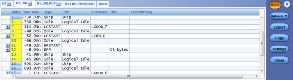
Table View of the Bus Protocol. The results table provides a protocol view of the bus and
with a mouse click allows correlation of what is happening in the physical layer to what is happening
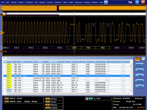
in the protocol layers.Protocol and Electrical Views of an HSS Bus. The data in the results table and the acquired
waveform are time correlated, enhancing the ability to identify possible causes of protocol errors due
to electrical signaling.
Both the 8b/10b serial bus trigger and the advanced search and mark feature on the oscilloscope are
integrated with the HSS protocol decode to quickly isolate events of interest in a HSS data stream.
User-selectable bandwidth limit filters
While wide bandwidth is needed to characterize your high-speed serial designs, certification testing
can require a specific instrument bandwidth appropriate for the signal's data rate in order to correlate
test results between different test labs. The MSO/DPO70000 Series feature user-selectable bandwidth
limiting filters. Using these bandwidth limit filters which range from 500 MHz to 32 GHz, you will
ensure that your measurement is done using the bandwidth specified by the industry standard.
Debugging
Throughout the design cycle, MSO/DPO70000 Series oscilloscopes provide
the ability to debug malfunctioning subsystems and isolate the cause. With the
high waveform capture rate of FastAcq® you can quickly identify signal
anomalies that occur intermittently – saving minutes, hours, or even days by
quickly revealing the nature of faults so sophisticated trigger modes can be
applied to isolate them. Using Pinpoint® triggers, infrequent events such as
glitches or signal runts caused by bus contention or signal integrity issues
can be captured, analyzed, and then eliminated.
FastAcq® – Expedites debugging by clearly showing imperfections
More than just color grading or event scanning, the FastAcq® proprietary DPX®
acquisition technology captures signals at more than 300,000 waveforms per second on all four channels
simultaneously, dramatically increasing the probability of discovering infrequent fault events. And with
a simple turn of the intensity knob you can clearly “see a world others don't see”, displaying the
complete picture of your circuit's operation. Some oscilloscope vendors claim high waveform capture
rates for short bursts of time, but only MSO/DPO70000 Series oscilloscopes, enabled by DPX®
technology, can deliver these fast waveform capture rates on a sustained basis.
Pinpoint® trigger
Whether you're trying to find a problem signal or need to isolate a section of a complex signal for
further analysis, like a DDR Read or Write burst, Tektronix
Pinpoint triggering provides the solution.
Pinpoint triggering allows selection of virtually all trigger types on both A
and B trigger events delivering the full suite of advanced trigger types for finding sequential trigger
events.
Pinpoint triggers provide trigger reset capabilities that begin the trigger
sequence again after a specified time, state, or transition so that even events in the most complex
signals can be captured. Other oscilloscopes typically offer less than 20 trigger combinations;
Pinpoint triggering offers over 1400 combinations, all at full performance.
Visual Trigger extends the Pinpoint Triggering's capabilities, adding another level of trigger
qualification to find important events in a wide variety of complex signals.
With Enhanced Triggering, trigger jitter is reduced to <100 fs. With this stability at the trigger
point, the trigger point can be used as a measurement reference.
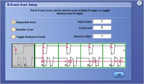
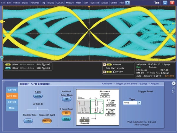
B scan event trigger
Users who wish to create eye diagrams from data bursts synchronized or initiated by an A event will
find the B Event Scan trigger function especially useful. B Event Scan is an A to B trigger sequence
that will trigger and capture burst event data of interest defined by the B Event setup menu. Captured
bits can be scanned in a sequential or randomized fashion, alternatively the trigger can toggle between
two successive B trigger events.
B Event Scan identifies specific events to build an eye diagram.Use B Event Scan trigger on DDR DQS edges used to construct an eye diagram of all bits in a
burst.
Logic pattern triggering
Logic pattern triggering allows logic qualification that controls when to look for faults and ignore
events that do not occur during the desired state. On the MSO70000 Series, up to 20-bit wide logic
pattern triggering enhances the
Pinpoint trigger capabilities by helping you isolate the specific system state
and analog events that are causing system failure.
Digital A then analog B triggering (MSO70000 Series only)
Advanced triggering capabilities include Digital A then Analog B to help you to identify a specific
digital pattern or system state and then wait for an analog event such as a runt pulse to trigger the
acquisition.
Integrated logic channels (MSO70000 Series only)
The MSO70000 Series extends the debug capabilities of a 4-channel oscilloscope with an additional 16
logic channels that can be used to provide system level context when the fault occurs. This context,
such as an illegal system state or error, may be the clue that leads to the root cause. When other
oscilloscopes require you to use a logic analyzer to see the digital data you need to solve your
debugging challenge, the MSO70000 Series can effectively debug and verify many digital timing issues in
the system more quickly and easily. With 80 ps timing resolution and channel-to-channel skews of as
little as 160 ps, the integrated logic channels allow you to view and measure time-correlated digital
and analog data in the same display window.
Integrated Logic Channels – Provide time-correlated analog and digital visibility for system
debugging.
FastFrame™
When the key events you are interested in are widely spaced in time, such as bursts of activity on a
bus, the
FastFrame segmented memory feature on the MSO/DPO70000 Series enables you to
capture the events of interest while conserving acquisition memory. Using multiple trigger events,
FastFrame captures and stores short bursts of signals and saves them as frames
for later viewing and analysis. On the MSO70000 Series,
FastFrame and bus or logic triggering enable you to capture your fastest, bursty
signals on the analog channels at the highest sample rate while the logic channel trigger recognizes the
bus cycle of interest. Capturing thousands of frames is possible, so long-term trends and changes in the
bursting signal can be analyzed. Signals captured with
FastFrame can also be post-processed using waveform averaging or envelope mode.
iCapture™ (MSO70000 Series only)
When an anomaly is seen on digital lines, iCapture delivers new insight into
the analog behavior of the digital signals. With iCapture, you can route any 4
of the 16 logic channels to the MSO70000 Series analog acquisition system so that these signals can be
viewed in finer detail. The unique multiplexer circuitry of iCapture provides
simultaneous digital and analog views of signals without needing to move the logic probe or double probe
the circuit.
Advanced search and mark
Isolating the key event causing your system failure can often be a tedious task. With the Advanced
Event Search and Mark feature standard on the MSO/DPO70000 Series, examining data and highlighting
important events, skipping the unimportant ones, and enhancing the comprehension of event relationships
is made easy. With ASM, you'll be able to navigate through long record length acquisitions effortlessly
and quickly locate the event you have been trying to find. Advanced searches can be defined individually
or using the scope's trigger settings as the definition for the search. Even Visual Trigger areas can be
used as part of the ASM criteria.
Advanced Search and Mark – Highlights important events and provides convenient previous and
next buttons and mouse clicks to navigate between events of interest effortlessly.
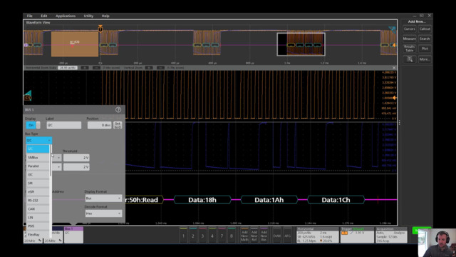
Embedded serial bus (I2C, SPI, RS-232/422/485, UART, USB) decoding and triggering
The MSO/DPO70000 Series instruments provide integrated support for a broad range of serial buses –
I2C, SPI, RS-232/422/485/UART, and USB. This support for up to 16 separate serial buses
enables you to monitor or debug subsystems and components, such as frequency synthesizers, D/A
converters, and Flash Memory that are controlled or monitored through serial control buses. While
monitoring or debugging these serial buses alone is relatively easy, decoding events on the serial bus
can also enable more complex system-level debugging. When you experience an issue with a higher-speed
serial interface, the clue to what is going wrong may be found by using the serial bus decode feature to
observe the data on your I2C, SPI, RS-232/422/485/UART, or USB interface.
Probing – analog and digital
Often the biggest challenge in debugging a system is getting access to the required signals. Tektronix
offers a wide array of probing solutions, including the P7700, P7600, and P7500
TriMode probing system with bandwidths that are perfectly matched to the
MSO/DPO70000 Series. These
TriMode probes allow you to switch among differential, single ended, and
common-mode measurements without moving the probe from its connection points. The P7700 and P7500 series
are compatible with all DPO/MSO70000C/DX/SX models. The P7600 series is compatible with DPO/MSO70000
DX/SX models, and combines low noise, 33 GHz bandwidth and the convenience of TriMode™ probing. The
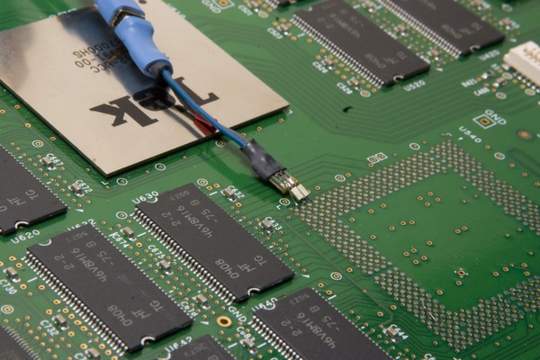
P7500 Series offers probes with performance from 4 GHz to 25 GHz and offers several low-cost solder tips
with quick connection features that allow moving the probe to various solder points fast and easy.
The low-cost solder tips available for the P7500 TriMode™ probes allow quick connection so
moving the probe to various solder points is fast and easy.
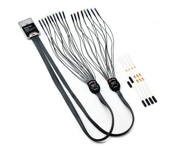
On the MSO70000 Series, the P6780 differential, P6750 high-density
D-Max, and P6717A general-purpose logic probes provide connectivity to low-speed
and high-speed digital signals with low loading, small size, and a range of accessories for soldering or
browsing.
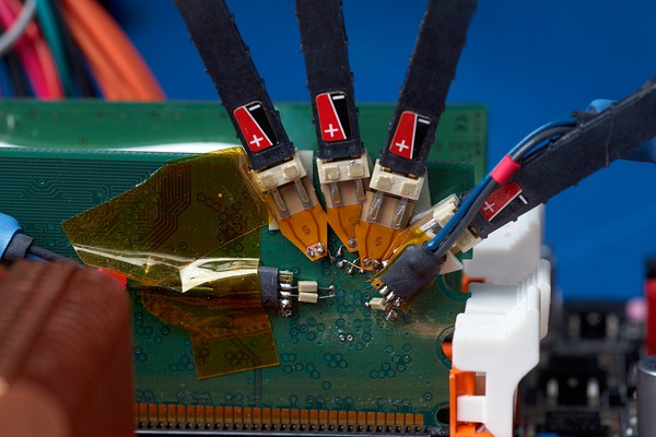
Solder tip accessories designed for the P6780 differential logic probes provide access to
signals on tightly spaced vias and fine-pitched components.
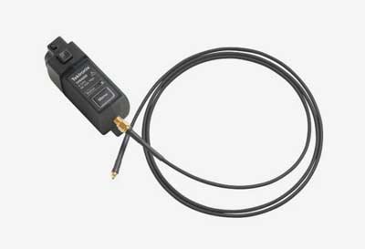
DPO7OE Series Optical Probes
The DPO7OE Series Optical probes can be used as an Optical Reference Receiver for high speed serial
data signals (using selectable Bessel-Thomson ORR filters), or can be used as a conventional O/E
converter for general wide-bandwidth optical signal acquisition. The DPO7OE Series (DPO7OE1 and DPO7OE2)
probes are compatible with DPO/MSO70000 C/DX/SX models. Connected to TekConnect channels for up to 33
GHz bandwidth.
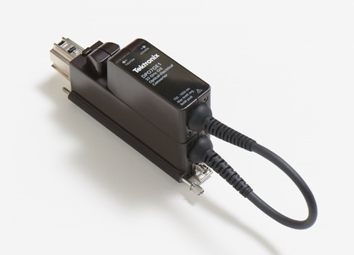
DPO7OE1 33 GHz Optical Probe
Production testing
In addition to assisting engineers with design tasks, the MSO/DPO70000 Series allow test engineers to
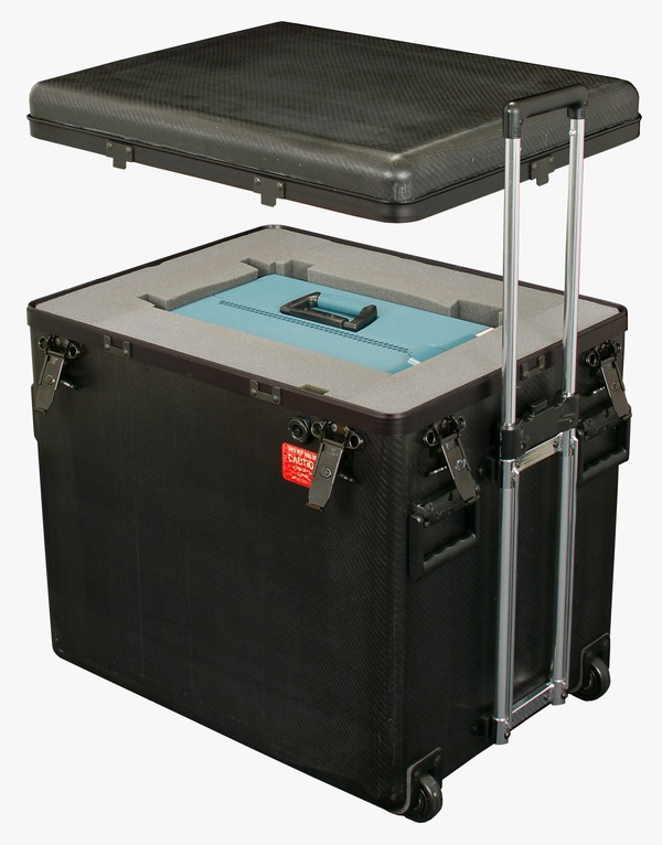
test analog and digital signals with a wide range of clock speeds and data rates. Rackmount options are
available for mounting the MSO/DPO70000 Series into an EIA standard 19 inch (487 mm) rack. An IEEE 488.2
standard GPIB interface is standard on all models.
LXI Class C
Using the LXI Web Interface, you can connect to the MSO/DPO70000 Series through a standard web browser
by simply entering the oscilloscope’s IP address in the address bar of the browser. The web interface
enables viewing of instrument status and configuration, as well as status and modification of network
settings. All web interaction conforms to the LXI Class C specification.
OpenChoice® analysis tools
The
OpenChoice Software allows you to customize your test and measurement system
with familiar analysis tools. The analysis and networking features of the
OpenChoice software add more flexibility to Tektronix MSO/DPO70000 Series
oscilloscopes: Using the fast embedded bus, waveform data can be moved directly from acquisition to
analysis applications on the
Windows desktop at much faster speeds than conventional GPIB transfers.
Implementation by Tektronix of industry-standard protocols, such as
TekVISA interface and ActiveX controls, are included for using and enhancing
Windows applications for data analysis and documentation. IVI instrument drivers
are included to enable easy communication with the oscilloscope using GPIB, RS-232, and LAN connections
from programs running on the instrument or an external PC.
The Application Development Kit (ADK) extends the
OpenChoice framework to support custom end-user and third-party application
development. ADK documentation describes how to implement the Data Store Public Interface to speed
internal transfer of waveform data through user-created data processing algorithms and display the
results in real time on the oscilloscope screen. The Data Store Public Interface is >2X faster than
traditional GPIB-based data transfer techniques. The Data Store Public Interface is accessible through
MathWorks
MATLAB or .NET languages such as C# or Visual Basic. Other features of the ADK
include a DPOJET plug-in that enables users to add custom measurements to this market-leading timing and
jitter analysis tool. The ADK provides comprehensive documentation and coding examples to aid the user
in developing their own unique analysis tool kit to quickly capture and analyze their signals.
Research
With industry-leading acquisition speed and signal-to-noise ratio performance, the MSO/DPO70000 Series
can provide researchers with tools that allow them to capture, display, and analyze high-speed and
transient signals with unmatched precision.
Full control of acquisition and display parameters
You have full control of the instrument's acquisition modes. Choose the mode you need to do your job
the fastest: Automatic, Constant Sample Rate, or Manual settings. When you are doing signal exploration
and want a lively signal, the default Automatic mode provides you with the liveliest display update
rate. If you want the highest real-time sample rate that will give you the most measurement accuracy,
then the Constant Sample Rate mode is for you. It will maintain the highest sample rate and provide the
best real-time resolution. Finally, the Manual mode ensures direct and independent control of the sample
rate and record length for applications requiring specific settings.
Document tools
The
OpenChoice architecture provides a comprehensive software infrastructure for
faster, more versatile operations. Data transfer utilities, such as the Excel or Word toolbar plug-ins
can be used to simplify analysis and documentation on the
Windows desktop or on an external PC.
Unmatched usability
The MSO/DPO70000 Series instruments excel in usability with a suite of productivity features, such as a
touch screen, flat menu structures, intuitive graphical icons, knob-per-channel vertical controls, right
clicks, mouse wheel operation, and familiar Windows-based controls.
Remote Desktop
When your oscilloscope is connected to a network, use the
Windows Remote Desktop utility to access your oscilloscope from across the lab
or across the globe.
MyScope® – Create your own control windows
Easily create your own personalized "toolbox" of oscilloscope features in a matter of minutes using a
simple, visual, drag-and-drop process. Once created, these custom control windows are easily accessed
through a dedicated
MyScope button and menu selection on the oscilloscope button/menu bar, just like
any other control window. You can make an unlimited number of custom control windows, enabling each
person who uses the oscilloscope in a shared environment to have their own unique control window.
MyScope control windows will benefit all oscilloscope users, eliminating the
ramp-up time that many face when returning to the lab after not using an oscilloscope for a while, and
enables the power user to be far more efficient. Everything you need is found in one control window
rather than navigating through multiple menus to repeat similar tasks.
Option asset management: floating or fixed
Many Tektronix application solutions and hardware options are enabled with an encrypted license key
that is entered through the oscilloscope's Utilities menu. You now have two options. The first option is
a fixed license applied to a specific scope serial number and is permanently enabled. A fixed license
cannot be moved from one oscilloscope to another.
The second option is a floating license. Floating licenses provide the capability to move a license-key
enabled option from one oscilloscope to another. This capability helps users with distributed teams and
several Tektronix DPO70000SX, MSO/DPO70000, or DPO7000, and MSO/DPO5000 Series oscilloscopes to better
manage their assets and deploy applications or other options such as extended memory to the oscilloscope
where it is needed.
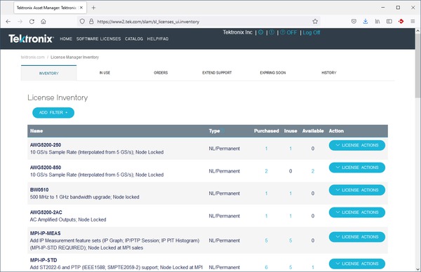
This view in the floating license system identifies the license's current user and location
allowing you to easily manage your floating license inventory.
Managing and deploying floating licenses uses an easy online licensing management system. All floating
license management functions are maintained on Tektronix secure servers and no infrastructure or your
company IT department involvement is necessary. Simply utilize your myTek account to access, track, and
deploy your oscilloscope floating-license enabled options.
Performance you can count on
Depend on
Tektronix to provide you with performance you can count on. All
Tektronix products are backed with industry-leading service and support.
Specifications
All specifications are guaranteed unless noted otherwise. All specifications apply to all models unless
noted otherwise.
Model overview
DPO70804C, MSO70804C
DPO71254C, MSO71254C
DPO71604C, MSO71604C
DPO72004C, MSO72004C
DPO72304DX, MSO72304DX
DPO72504DX, MSO72504DX
DPO73304DX, MSO73304DX
Analog channels
4
4
4
4
4
4
4
Digital channels (MSO70000 Series only)
16
16
16
16
16
16
16
Analog bandwidth (user-selectable DSP enhance) (–3 dB)
8 GHz
12.5 GHz
16 GHz
20 GHz
23 GHz (2 Ch)
23 GHz (4 Ch)
25 GHz (2 Ch)
23 GHz (4 Ch)
33 GHz (2 Ch)
23 GHz (4 Ch)
Hardware Analog Bandwidth (-3 dB)
8 GHz
12.5 GHz
16 GHz (typical)
16 GHz (typical)
23 GHz
25 GHz
33 GHz
Rise time (typical)
10% to 90%: 49 ps
20% to 80%: 34 ps
10% to 90%: 32 ps
20% to 80%: 22 ps
10% to 90%: 24.5 ps
20% to 80%: 17 ps
10% to 90%: 18 ps
20% to 80%: 14 ps
10% to 90%: 17 ps
20% to 80%: 13 ps
10% to 90%: 16 ps
20% to 80%: 12 ps
10% to 90%: 13 ps
20% to 80%: 9 ps
Sample rate (1, 2 ch) (maximum sample rate is 50 GS/s on digital channels routed to an analog
channel through the iCapture™ analog mux)
25 GS/s
100 GS/s
100 GS/s
100 GS/s
100 GS/s
100 GS/s
100 GS/s
Sample rate (3, 4 ch)
25 GS/s
50 GS/s
50 GS/s
50 GS/s
50 GS/s
50 GS/s
50 GS/s
Sample rate (ET/IT mode)
5 TS/s
10 TS/s
10 TS/s
10 TS/s
10 TS/s
10 TS/s
10 TS/s
Record length, points (each channel, standard)
31.25 M
62.5 M (MSO70000 Series)
31.25 M
62.5 M (MSO70000 Series)
31.25 M
62.5 M (MSO70000 Series)
31.25 M
62.5 M (MSO70000 Series)
31.25 M
62.5 M (MSO70000 Series)
31.25 M
62.5 M (MSO70000 Series)
31.25 M
62.5 M (MSO70000 Series)
Record length (each channel, Opt. 5XL, DPO70000 series)
62.5 M
62.5 M
62.5 M
62.5 M
62.5 M
62.5 M
62.5 M
Record length (each channel, Opt. 10XL)
125 M
125 M
125 M
125 M
125 M
125 M
125 M
Record length (each channel, Opt. 20XL)
N/A
250 M
250 M
250 M
250 M
250 M
250 M
Record length (each channel, Opt. 50XL)
N/A
N/A
N/A
N/A
500 M each channel, 1G on 2 channels
500 M each channel, 1G on 2 channels
500 M each channel, 1 G on 2 channels
Timing resolution
40 ps
(25 GS/s)
10 ps
(100 GS/s)
10 ps
(100 GS/s)
10 ps
(100 GS/s)
10 ps
(100 GS/s)
10 ps
(100 GS/s)
10 ps
(100 GS/s)
Duration at highest sample rate (standard)
1.25 ms
2.5 ms (MSO70000 Series)
0.31 ms
0.61 ms (MSO70000 Series)
0.31 ms
0.61 ms (MSO70000 Series)
0.31 ms
0.61 ms (MSO70000 Series)
0.31 ms
0.61 ms (MSO70000 Series)
0.31 ms
0.61 ms (MSO70000 Series)
0.31 ms
0.61 ms (MSO70000 Series)
Duration at highest sample rate (Opt. 5XL, DPO70000 series)
2.5 ms
0.63 ms
0.63 ms
0.63 ms
0.63 ms
0.63 ms
0.63 ms
Duration at highest sample rate (Opt. 10XL)
5.0 ms
1.3 ms
1.3 ms
1.3 ms
1.3 ms
1.3 ms
1.3 ms
Duration at highest sample rate (Opt. 20XL)
—
2.5 ms
2.5 ms
2.5 ms
2.5 ms
2.5 ms
2.5 ms
Duration at highest sample rate (Opt. 50XL)
—
—
—
—
5 ms each channel, 10 ms 2 channels
5 ms each channel, 10 ms 2 channels
5 ms each channel, 10 ms 2 channels
Vertical noise (% of full scale) (50 mV/div, bandwidth filter on, max sample rate) (typical)
0.35%
0.36%
0.36%
0.56%
0.58%
0.58%
0.58%
Time base range (Auto mode)
20 ps/div to 1000 s/div
10 ps/div to 1000 s/div
10 ps/div to 1000 s/div
10 ps/div to 1000 s/div
10 ps/div to 1000 s/div
10 ps/div to 1000 s/div
10 ps/div to 1000 s/div
Timing resolution (ET/IT mode)
200 fs
100 fs
100 fs
100 fs
100 fs
100 fs
100 fs
Delta time measurement accuracy (RMS over <100 ns Duration; Single Shot; Signal Rise Time =
1.2 × Scope Rise Time; 100 mV/div, bandwidth filter on, max sample rate)
1.24 ps
1.23 ps
1.15 ps
1.43 ps
639 fs
639 fs
555 fs
Jitter noise floor (with BWE enabled) (typical)
300 fs
270 fs
270 fs
290 fs
<380 fs
<365 fs
<325 fs
Vertical system – Analog channels
Bandwidth limit
Depending on instrument model: 33 GHz to 1 GHz in 1 GHz steps, or 500 MHz
Depending on instrument model, hardware-only bandwidth settings at 33, 25, 23, 20, 16, 12.5, 8
GHz
Channel-to-Channel isolation
Any two channels at equal vertical scale
0 GHz to 10 GHz: ≥120:1
>10 GHz to 12 GHz: ≥80:1
>12 GHz to 15 GHz: ≥50:1
>15 GHz to 20 GHz: ≥25:1
>20 GHz to 33 GHz: ≥20:1
DC gain accuracy
±2% (of reading)
Channel delay (typical)
≤10 ps for any two channels at equal V/div and coupling on C models
≤1 ps for any two channels at equal V/div and coupling on DX models
Effective number of bits (typical)
5.5 bits at 50 mV/div, bandwidth filter on, max bandwidth up to 13 GHz, max sample rate
Signal-to-Noise ratio (typical)
34 dB
Input coupling
DC (50 Ω), GND
Input resistance selection
50 Ω ±3%, 1 MΩ with TCA-1MEG adapter
Input sensitivity range
23 GHz, 25 GHz, and 33 GHz models
6.25 mV/div to 600 mV/div (62.5 mV to 6 V full scale)
20 GHz models
20 to 500 mV/div (200 mV to 5 V full scale)
10 mV/div at 18 GHz (100 mV full scale)
All other models
10 mV/div to 500 mV/div (100 mV to 5 V full scale)
Maximum input voltage, 50 Ω
Also determined by TekConnect® accessory.
23 GHz, 25 GHz, and 33 GHz models
≤1.2 VFS: ±1.5 V relative to the termination bias (30 mA maximum), ±5 V absolute
maximum input.
>1.2 VFS: 8.0 V.
All other models
<5.0 VRMS for ≥100 mV/div; 1.0 VRMS for <100 mV/div
Termination voltage range
23 GHz, 25 GHz, and 33 GHz models
≤1.2 VFS: -3.5 V to +3.5 V
>1.2 VFS: 0 V.
All other models
0 V only
Offset accuracy
10 mV/div to 99.5 mV/div
±(0.35% (offset value-position) + 1.5 mV + 1% of full scale)
100 mV/div to 500 mV/div
±(0.35% (offset value-position) + 7.5 mV + 1% of full scale)
20 kΩ to ground per side or 40 kΩ differential mode ± 2.0%, 0.5 pF
With P6750 or P6717A logic probe
20 kΩ ± 1.0%, 3 pF
Trigger clock/qualifier input
1
Vertical resolution
1 bit
Thresholds
One per channel, independently set
Threshold accuracy
±75 mV + 3% of threshold setting
Threshold resolution
5 mV
Threshold voltage range
With P6780 logic probe
–2 to +4.5 V
With P6750 or P6717A logic probe
–1.5 to +4.0 V
Minimum voltage swing
300 mVp-p
Maximum input voltage
±15 V nondestruct
Horizontal system
Channel-to-Channel deskew range
±75 ns
Time base accuracy
±1.5 ppm initial accuracy, aging <1 ppm per year
Time base delay time range
–5.0 ks to 1.0 ks
Trigger jitter
<100 fsRMS (1.3 psRMS [typical] with enhanced triggering off)
Acquisition system - Analog channels
Acquisition modes
Sample
Acquires and displays sampled values
Average
From 2 to 10,000 waveforms can be included in an average waveform
Envelope
From 1 to 2×10⁹ waveforms included in min-max envelope
Hi-Res
Real-time boxcar averaging reduces random noise and increases resolution
Peak detect
Capture and display narrow glitches at all real-time sampling rates. Glitch widths: 1 ns at
≤125 MS/s; 1/sample rate at ≥250 MS/s
FastAcq®
FastAcq® optimizes the instrument for analysis of dynamic signals and capture of
infrequent events, capturing >300,000 wfms/s on all TekConnect channels simultaneously,
standalone configuration only
FastFrame™
Acquisition memory divided into segments; maximum trigger rate >310,000 waveforms per
second. Time of arrival recorded with each event. Frame finder tool helps to visually identify
transients. TekConnect channels only, standalone configuration only
Roll mode
Scrolls sequential waveform points across the display in a right-to-left rolling motion. Works
at sample rates up to 10 MS/s with a maximum record length of 40 MS. TekConnect channels only,
standalone configuration only
Waveform database
Accumulates waveform data providing a three-dimensional array of amplitude, time, and counts.
TekConnect channels only, standalone configuration only
Acquisition system – Digital channels
Maximum sample rate (all channels)
12.5 GS/s
Timing resolution
80 ps
Channel-to-Channel timing uncertainty
<160 ps
Minimum detectable pulse width
<400 ps
Maximum number of buses
16
Number of channels per bus
Up to 24 (16 logic, 4 analog, 4 math)
Pinpoint® trigger system
Trigger sensitivity
Internal DC coupled
4% of full scale from DC to 50 MHz
10% of full scale at 4 GHz
20% of full scale at 8 GHz
50% of full scale at 11 GHz
Aux input 50 Ω (external trigger)
250 mV from DC to 50 MHz, increasing to 350 mV at 1.0 GHz
A event and delayed B event trigger types
Edge, glitch, width, runt, timeout, transition time, logic pattern, logic state, setup/hold,
window - all except edge, pattern, and state can be logic state qualified by up to two channels
Main trigger modes
Auto, Normal, and Single
Trigger sequences
Main, Delayed by Time, Delayed by Events, Reset by Time, Reset by State, Reset by Transition. All
sequences can include a separate horizontal delay after the trigger event to position the
acquisition window in time
Trigger coupling
DC, AC (attenuates <100 Hz)
HF Rej (attenuates >20 kHz)
LF Rej (attenuates <200 kHz)
Noise Reject (reduces sensitivity)
RF coupling (increases trigger sensitivity and bandwidth at the highest operating frequencies)
Trigger holdoff range
250 ns min to 12 s max
Trigger level range
Any channel
±120% of full scale from center of screen
Auxiliary input
±5 V
Line
0 V, not settable
Clock recovery system
DPO Models
Requires Option ST6G or Option MTH
MSO Models
Standard
Clock recovery phase locked loop bandwidth
Fixed at FBaud/1600
Clock recovery jitter (RMS)
<0.25% bit period + 2 psRMS for PRBS data patterns
<0.25% bit period + 1.5 psRMS for repeating "0011” data pattern
Minimum signal amplitude needed for clock recovery
1 divp-p up to 1.25 Gbaud
1.5 divp-p above 1.25 Gbaud
Tracking/Acquisition range
±2% of requested baud
Clock recovery frequency range
1.5 MBaud to 3.125 GBaud. Recovered clock and regenerated data available for use with a BERT.
Serial pattern trigger
DPO Models
Requires Option ST6G
MSO Models
Standard
NRZ-Encoded Data
Up to 64 bit serial word recognizer, bits specified in binary (high, low, don't care) or hex
format
Trigger on NRZ-encoded data up to 1.25 GBaud
8b/10b-Encoded Data
Trigger on 8b/10b-encoded data at the following rates: 1.25 to 1.65, 2.1 to 3.2, 3.8 to 5.1,
and 5.4 to 6.25 GBaud.
Pattern length up to 40 bits (1 to 4 valid 10-bit characters)
Alignment character is K28.5 (either disparity)
Communications-related triggers
Support for AMI, HDB3, BnZS, CMI, MLT3, and NRZ encoded communications signals. Select among
isolated positive or negative one, zero pulse form, or eye patterns as applicable to the standard.
DPO Models
Requires Option MTH
MSO Models
Standard
Bus triggers maximum toggle rate
I2C, SPI, RS-232/422/485/UART: 10 Mb/s
USB: low-speed, full-speed
CAN: 1 Mb/s
LIN: 100 kb/s
MIL-STD-1553B: 2 Mb/s
Logic pattern trigger (MSO Models)
Threshold range
P6780: –2 to +4.5 V
P6717A/P6750: –1.5 to +4 V
Threshold accuracy
±100 mV + 3% of threshold setting
Enhanced triggering
Enhanced triggering corrects the difference in timing between the trigger path and the acquired
data path (supports all Pinpoint trigger types on both A- and B-Events except pattern trigger);
Default On (user-selectable); Not available in FastAcq mode.
Line trigger
Trigger on power line signal. Level fixed at 0 V.
Visual Trigger
Requires Option VET
Max number of areas
8
Area shapes
Rectangle, Triangle, Trapezoid, Hexagon, user defined shapes (can have >40 vertices)
Compatibility
Visual Trigger qualification is compatible with all trigger types and all trigger sequences
Low-speed or Full-speed: Trigger on Sync, Reset, Suspend, Resume, End of Packet, Token
(Address) Packet, Data Packet, Handshake Packet, Special Packet, Error.
Trigger on Patterns (including ordered sets), Character/Symbol, Error, Control Characters
(gen 1 and gen 2 rates only)
Edge
X
X
Positive or negative slope on any channel or front-panel auxiliary input. Coupling includes
DC, AC, noise reject, HF reject, and LF reject.
B Event Scan
X
B Event Scan is an A to B trigger sequence that will trigger and capture burst event data of
interest as defined in the B Event Scan setup menu. Captured bits can be scanned in a
sequential or randomized fashion, and alternatively the trigger can toggle between two
successive B trigger events. Eye diagrams can be constructed with burst data acquired as a
result of scanning B Event.
Glitch
X
X
Trigger on or reject glitches of positive, negative, or either polarity. Minimum glitch
width is 150 ps (typical) with rearm time of 300 ps.
Pattern
X
X
Trigger when pattern goes false or stays true for specified period of time. Pattern (AND,
OR, NAND, NOR) specified for four input channels (and 16 logic channels on the MSO70000
Series) defined as high, low, or don't care.
Runt
X
Trigger on a pulse that crosses one threshold but fails to cross a second threshold before
crossing the first again. Event can be time- or logic-qualified.
Trigger on NRZ-encoded data up to 6.25 Gbaud; above 1.25 Gbaud requires 8b/10b encoded data.
Includes pattern lock triggering to capture repeated acquisitions of long serial test patterns
up to 6.25 Gb/s.
Setup/Hold
X
Trigger on violations of both setup time and hold time between clock and data present on any
two input channels.
State
X
X
Any logical pattern of channels (1, 2, 3) (and 16 logic channels on the MSO70000 Series)
clocked by edge on channel 4. Trigger on rising or falling clock edge.
Timeout
X
X
Trigger on an event which remains high, low, or either, for a specified time period.
Selectable from 300 ps.
Transition
X
Trigger on pulse edge rates that are faster or slower than specified. Slope may be positive,
negative, or either.
Trigger when the Visual Trigger expression is satisfied.
Width
X
X
Trigger on width of positive or negative pulse either within or out of selectable time
limits (down to 150 ps).
Window
X
Trigger on an event that enters or exits a window defined by two user-adjustable thresholds.
Event can be time or logic qualified.
Waveform analysis
Search and Mark Events
Search for edges, glitches, or pulses of specified width. Any events found matching the search
criteria are marked and placed in the Event table. The search can use positive/negative slopes or
both on any channels.
When an event of interest is found, other similar events can be found using "Mark All Trigger
Events in Record" in the Pinpoint trigger control windows.
The Event table summarizes all found events. All events are time stamped in reference to trigger
position. Users can choose to stop acquisitions when an event is found.
Waveform measurements
Automatic measurements
53, of which 8 can be displayed on-screen at any one time; measurement statistics,
user-definable reference levels, measurement within gates isolating the specific occurrence
within an acquisition to measure
The DPOJET Jitter and Eye Analysis application offers additional automated and advanced
measurements such as jitter.
Rise Time, Fall Time, Positive Width, Negative Width, Positive Duty Cycle, Negative Duty
Cycle, Period, Frequency, Delay
Combination
Area, Cycle Area, Phase, Burst Width
Histogram related
Waveform Count, Hits in Box, Peak Hits, Median, Maximum, Minimum, Peak-to-Peak, Mean (μ),
Standard Deviation (sigma), μ +1sigma, μ +2sigma, μ +3sigma
Bus decoding
Parallel
Data from selected channels is grouped as a parallel, multichannel bus and displayed as a
single bus value. Display can be binary, hexadecimal, or symbolic formats
Rear panel. BNC connector, 0 to 3 V; default output is A-Event Trigger low true
Probe calibration output
Front panel. BNC connector, ±10 V DC for DC probe calibration (signal available only during probe
calibration)
Fast edge output
Front panel. SMA connector provides fast edge signal. 1 kHz ±20%; 810 mV (base to top) ±20% into
≥10 kΩ load; 440 mV ±20% into a 50 Ω load
Recovered clock output
Front panel. SMA connector, ≤1.25 Gb/s, Output swing ≥130 mVp-p into 50 Ω at 1.25 Gb/s.
Requires Option ST6G or Option MTH to enable on DPO70000 Series, standard on MSO70000 Series
Recovered data output
Front panel. SMA connector, ≤1.25 Gb/s, Output swing of 1010 repeating pattern 200 mV into 50 Ω at
1.25 Gb/s. Requires Option ST6G or Option MTH to enable on DPO70000 Series, standard on MSO70000
Series
USB interface
Front panel: Two USB 2.0 ports on 23, 25, and 33 GHz models, one on all others. Allows connection
of USB keyboard, mouse, or storage device
Rear panel: Four USB ports, two are USB 3.0. Allows connection of USB keyboard, mouse, or storage
devices
LXI web interface (LAN eXtensions for instrumentation)
Class: LXI Class C
Version: 1.3
Audio input/output
Rear panel. Miniature phone jacks for stereo microphone input and stereo line output
External time base reference in
Rear panel. BNC connector; allows time base system to phase lock to external 10/100 MHz reference.
Optimized (by using a software switch) for either a highly stable clock or tracking mode
GPIB interface
Rear panel. IEEE 488.2 standard
Keyboard port
Rear panel. PS/2 compatible
LAN port
Rear panel. RJ-45 connector, supports 10BASE-T, 100BASE-T, and 1000BASE-T
Mouse port
Rear panel. PS/2 compatible
eSATA port
Rear panel. External SATA interface for eSATA storage devices
Power
100 to 240 VRMS, ±10%, 50/60 Hz; 115 VRMS ±10%, <870 W, 400 Hz; CAT II,
<1100 VA typical
Video out port
Connect to show the oscilloscope display, including live waveforms on an external monitor or
projector. The primary Windows® desktop can also be displayed on an external monitor using these
ports.
Alternatively, the ports can be configured to show the secondary Windows® desktop (also called
extended desktop or dual-monitor display)
Extended record length - 125M/Ch for DPO units w/ option DSA
Opt. 520XL
Extended record length - 250M/Ch for DPO units w/ option DSA
Opt. 550XL
Extended record length - 500M/Ch for DPO DX units w/ option DSA
Storage options
Option
Description
Opt. SSD
Solid State Drive assembly - additional customer-installable removable drive with Microsoft
Windows 10 OS, TekScope and applications software installed
Trigger and search options
Option
Description
Opt. LT
Waveform Limit Testing
Opt. MTH
Mask Testing, Includes Hardware Clock Recovery
Opt. ST6G
8b/10b Serial Protocol Trigger and Decode up to 6.25Gb/s
Advanced analysis options
Option
Description
Opt. BRR
Automotive Ethernet (100BASE-T1, 1000BASE-T1) TekExpress Automated Compliance Test Solution
40GBASE-CR4 Debug and Automated Compliance Solution
Floating license options
Floating licenses offer an alternative method to manage your Tektronix asset. Floating licenses
allow license-key enabled options to be easily moved among all your MSO/DPO70000, DPO7000, and
MSO/DPO5000 Series oscilloscopes. Floating licenses are available for the license-key enabled
options listed below.
License, floating; Serial Protocol Trigger and Decode
DPOFL-PWR
License, floating; Power Measurement and Analysis Software
DPOFL-SAS3
License, floating; SAS-3 TX Compliance Test Application (requires Option DJA and Option 2XL
or higher, for models of bandwidth ≥20 GHz only). Compatible with all DPO/MSO70000C/DX series
Oscilloscope.
DPOFL-SAS3-TSG
License, floating; SAS-3 Automated TX Compliance Test Application. Compatible with all
DPO/MSO70000C/DX series Oscilloscope.
DPOFL-SAS3-TSGW
License, floating; SAS-3 WDP Transmitter Measurements. Compatible with all DPO/MSO70000C/DX
series Oscilloscope.
DPOFL-SAS4-TSG
SAS4 DPOJET Essentials
DPOFL-SATA-DHB
License, floating; SATA TekExpress SATA SW Bundle (TSG and RSG for Hosts or Devices).
Compatible with all DPO/MSO70000C/DX series Oscilloscope.
DPOFL-SATA-RSG
License, floating; SATA RSG/RMT Receiver Tests for TekExpress. Compatible with all
DPO/MSO70000C/DX series Oscilloscope.
DPOFL-SATA-R-UP
TEKEXP Upgrade for SATA RSG/RMT Receiver Tests for TekExpress. Compatible with all
DPO/MSO70000C/DX series Oscilloscope.
DPOFL-SATA-TSG
License, floating; SATA PHY/TSG/OOB Transmitter Tests for TekExpress. Compatible with all
DPO/MSO70000C/DX series Oscilloscope.
DPOFL-SC
License, floating; SignalCorrect Cable, Channel, and Probe Compensation Software
License, floating; Frequency and Phase Settling Time Measurements (requires Option SVE)
DPOFL-SWX-DP
License, floating; Switch Matrix option for DisplayPort testing. Compatible with all
DPO/MSO70000SX series Oscilloscope.
DPOFL-SWX-PCE
Switch Matrix for PCIE - Multi Lane Automation
DPOFL-TBT-TX
License, floating; Thunderbolt Transmitter Characterization, Debug, and Compliance Testing
(requires Option DJA and Option 2XL or higher, for models of bandwidth ≥16 GHz only)
DPOFL-UHS-2
License, floating; UHS-2 - UHS-II Automated Compliance and Margin Test Solution for Host and
Device - transmitter and receiver (for models of bandwidth ≥6 GHz only)
DPOFL-USB-TX
License, floating; USB 3.0 Automated TX Compliance Test Application (requires Option DJA,
for models of bandwidth ≥8 GHz only). Compatible with all DPO/MSO70000C/DX series
Oscilloscope.
DPOFL-USB-TX-UP
Floating License Upgrade from TEKEXP USB-TX (dongle-based licensing) to DPOFL-USB-TX.
Compatible with all DPO/MSO70000C/DX series Oscilloscope.
DPOFL-USB2
License, floating; USB 2.0 Automated Compliance Test Application. Compatible with all
DPO/MSO70000C/DX series Oscilloscope.
DPOFL-USBPWR
License, floating; USB Power Adapter/EPS Compliance Automated Test Solution (not supported
on 70000D models). Compatible with all DPO/MSO70000C/DX series Oscilloscope.
DPOFL-USBSSP-TX
License, floating; USB 3.2 Automated TX Compliance Test Application. Compatible with all
DPO/MSO70000C/DX series Oscilloscope.
DPOFL-USBSSP-UP
Floating License Upgrade from Floating USB TX to Floating USB SSP TX
DPOFL-VET
License, floating; Visual Trigger
DPOFL-XGBT2
License, floating; TekExpress Automated 10GBASE-T Solution. Compatible with all
DPO/MSO70000C/DX series Oscilloscope.
DPOFL-XL02
License, floating; Extended record length – 31.25 M Samples/Ch
DPOFL-XL05
License, floating; Extended record length – 62.5 M Samples/Ch
DPOFL-XL010
License, floating; Extended record length – 125 M Samples/Ch
DPOFL-XL020
License, floating; Extended record length – 250 M Samples/Ch (for models of bandwidth ≥12.5
GHz only)
DPOFL-XL050
License, floating; Extended record length - 500 M Samples each Ch, 1 G Samples on 2 Ch (DX
models only)
DPOFL-10G-KR
License, floating; 10GBASE-KR/KR4 Compliance and Debug Solution (requires Option DJA and
Option SR-CUST; for models of bandwidth ≥16 GHz only)
The MSO/DPO70000 Series instruments can be easily upgraded after initial time of purchase. To upgrade
an existing MSO/DPO70000, order DPO-UP and an option listed below. For example, to add option DDRA,
DDR Memory Technology Analysis Package, order DPO-UP DDRA.
Memory upgrades for DPO70000 Series
XL02
From standard record length to Opt. 2XL Configuration
XL05
From standard record length to Opt. 5XL Configuration
XL010
From standard record length to Opt. 10XL Configuration
XL020
From standard record length to Opt. 20XL Configuration
Memory upgrades for MSO/DPO70000 Series
XL25
From Opt. 2XL record length to Opt. 5XL
XL210
From Opt. 2XL record length to Opt. 10XL
XL220
From Opt. 2XL record length to Opt. 20XL
XL250
From Opt. 2XL record length to Opt. 50XL
XL510
From Opt. 5XL record length to Opt. 10XL
XL520
From Opt. 5XL record length to Opt. 20XL
XL550
From Opt. 5XL record length to Opt. 50XL
XL1020
From Opt. 10XL record length to Opt. 20XL
XL1050
From Opt. 10XL record length to Opt. 50XL
XL2050
From Opt. 20XL record length to Opt. 50XL
Trigger and search upgrades for MSO/DPO70000 Series
LT
Waveform Limit Testing
MTH
Mask Testing, Includes Hardware Clock Recovery
ST6G
8b/10b Serial Protocol Trigger and Decode up to 6.25 Gb/s
STU
Serial Pattern triggering up to 6.25Gb/s (Requires Opt. PTH)
Advanced analysis upgrades for MSO/DPO70000 Series
BRR
Automotive Ethernet (100BASE-T1, 1000BASE-T1) TekExpress Automated Compliance Test Solution
Additional Windows 10 SSD drive. For units shipped with Windows 10, or to upgrade from
Windows 7 to Windows 10. Microsoft Windows 10 OS, TekScope, and applications software
installed.
Order DPO7SSD-W10, do not order DPO-UP for this SSD.
Investment protection options
As signals get faster and new standards are developed, your investment in an MSO/DPO70000 Series
instrument can evolve with your needs. You can upgrade the bandwidth of the unit you own today. You
can take advantage of MSO/DPO70000 series performance improvements by upgrading your existing unit
to a new series, or adding MSO features to your current DPO model. Contact your local Tektronix
representative to discuss the full range of options available to ensure your MSO/DPO70000 series
oscilloscope has the tools you need for your next project.
Language options
Opt. L0
English manual
Opt. L1
French manual
Opt. L3
German manual
Opt. L5
Japanese manual
Opt. L7
Simplified Chinese manual
Opt. L8
Traditional Chinese manual
Opt. L9
Korean manual
Opt. L10
Russian manual
Opt. L99
No manual
Power plug options
Opt. A0
North America power plug (115 V, 60 Hz)
Opt. A1
Universal Euro power plug (220 V, 50 Hz)
Opt. A2
United Kingdom power plug (240 V, 50 Hz)
Opt. A3
Australia power plug (240 V, 50 Hz)
Opt. A5
Switzerland power plug (220 V, 50 Hz)
Opt. A6
Japan power plug (100 V, 50/60 Hz)
Opt. A10
China power plug (50 Hz)
Opt. A11
India power plug (50 Hz)
Opt. A12
Brazil power plug (60 Hz)
Opt. A99
No power cord
Service options
Opt. C3
Calibration Service 3 Years
Opt. C5
Calibration Service 5 Years
Opt. D1
Calibration Data Report
Opt. D3
Calibration Data Report 3 Years (with Opt. C3)
Opt. D5
Calibration Data Report 5 Years (with Opt. C5)
Opt. G3
Complete Care 3 Years (includes loaner, scheduled calibration, and more)
Opt. G5
Complete Care 5 Years (includes loaner, scheduled calibration, and more)
Opt. IF
Upgrade Installation Service
Opt. R3
Repair Service 3 Years (including warranty)
Opt. R5
Repair Service 5 Years (including warranty)
Recommended accessories
Probes
DPO7OE1
33 GHz optical probe
DPO7OE2
59 GHz optical probe
P7633
33 GHz Low Noise TriMode™ Probe
P7630
30 GHz Low Noise TriMode™ Probe
P7625
25 GHz Low Noise TriMode™ Probe
P7720
20 GHz TriMode Probe
P7716
16 GHz TriMode Probe
P7713
13 GHz TriMode Probe
P7708
8 GHz TriMode Probe
P7520A
25 GHz TriMode™ probe
P7516
16 GHz TriMode™ probe
P7513A
13 GHz TriMode™ differential probe
P7313SMA
13 GHz TriMode™ differential SMA probe
P7508
8 GHz TriMode™ probe
P7506
6 GHz TriMode™ probe
P7504
4 GHz TriMode™ probe
P6780
Differential Input Logic probe
P6750
D-Max® Technology Logic Probe
P6717A
General-purpose Logic probe
P6251
DC to 1 GHz, 42 V, differential probe (requires TCA-BNC adapter)
TCPA300/TCPA400 Series
Current measurement systems
P5200A/P5205A/P5210A
High-voltage differential probes
P77DESKEW
P7700 Probe Deskew Fixture for SMA, solder-down, and browser connections
067-2431-xx
Probe Deskew Fixture for SMA or solder-down connections (up to 30 GHz)
067-0484-xx
Analog Probe Calibration and Deskew Fixture (4 GHz)
067-1586-xx
Analog Probe Deskew Fixture (>4 GHz)
067-1686-xx
Power Deskew Fixture
Adapters
TCA-1MEG
TekConnect® high-impedance buffer amplifier. Includes P6139B passive probe
TCA-292MM
TekConnect® to 2.92 mm adapter (20 GHz bandwidth)
TCA-292D
TekConnect® to 2.92 mm adapter (33 GHz bandwidth)
TCA-BNC
TekConnect® to BNC adapter
TCA-N
TekConnect® to N adapter
TCA-SMA
TekConnect® to SMA adapter
TCA-VPI50
50 Ω TekVPI to TekConnect adapter
TCA75
23 GHz precision TekConnect® 75 Ω to 50 Ω adapter with 75 Ω BNC input connector
Cables
DPOACQSYNC
Multi-scope synchronization kit (includes fast edge source, cables, power splitters, carrying
case)
Test fixtures that complement the use of the TekEXP-XGbT solution
Transit Case (carbon fiber).
Other
016-1985-xx
Rackmount Kit
077-0076-xx
Service Manual, pdf on hard drive
016-2039-00
Transit Case (metal frame, wood panels)
016-2043-00
Transit Case (carbon fiber)
TF-TEKPROTECT ESD Protection Tester:
MSO/DPO70000C instruments include TekProtect circuitry designed to stop EOS/ESD events from
reaching analog channel preamp inputs, while still allowing normal signals to pass. TekProtect
should be checked regularly with the TF-TEKPROTECT ESD Protection Tester to ensure the device
is still working.
Engineers rely on an oscilloscope throughout their design cycle, from prototype turn-on to production
testing. The MSO/DPO70000 Series oscilloscopes unique capabilities combined with exceptional signal
acquisition performance and analysis accelerate your measurement tasks.
Key performance specifications
Up to 33 GHz analog bandwidth and rise time as fast as 9 ps. Enables measurement on the latest
high-speed serial standards
True 33 GHz Real-time Analog Bandwidth on 2 Channels with 33 GHz models
Industry-leading sample rate and timing resolution
100 GS/s on 2 Channels (33, 25, 23, 20, 16, and 12.5 GHz models)
Four-channel Simultaneous Performance
Up to 23 GHz Bandwidth
Up to 50 GS/s Real-time Sample Rate
Up to 500 Megasample Record Length with MultiView Zoom™ for quick navigation
Fastest Waveform Capture Rate with >300,000 wfms/s maximum per channel
16 Logic Channels with 80 ps Timing Resolution for Debug of digital and analog signals
(MSO70000 Series only)
Unique iCapture® capability enables viewing analog characteristics of digital channels with
single probe connection
6.25 Gb/s Real-time Serial Trigger – Assures triggering on the first instance of a specified NRZ
or 8b/10b pattern to allow isolation of pattern-dependent effects
Application Support for High-speed Serial Industry Standards, wideband RF, Power supplies, and
memory – Enables standard-specific certification, measurement automation, and ease of use
Key features
Superior signal integrity and excellent signal-to-noise ratio – observe the truest
representation of your waveform
Pinpoint triggering – minimize time spent trying to acquire problem
signals for efficient troubleshooting and shortened debug time
Visual Trigger – precisely qualify triggers and find unique events in complex waveforms
Search and Mark – provides waveform or serial bus pattern matching and software triggers for
signals of interest
Automated Serial Analysis options for PCI Express, 8b/10b encoded serial data, I2C,
SPI, CAN, LIN, FlexRay, RS-232/422/485/UART, USB 2.0, HSIC, MIL-STD-1553B, and MIPI®
C-PHY, D-PHY and M-PHY
P7700, P7600, and P7500
TriMode probing system – perfectly matched signal connectivity, with
calibration to probe tip
P6780, P6750, and P6717A high-performance 17-channel logic probes with bandwidths up to 2.5 GHz
for connections to today's fast digital signals (MSO70000 Series only)
Connectivity
USB 2.0 host port on both the front panel and rear panel for quick and easy data storage,
printing, and connecting a USB keyboard
Integrated 10/100 Ethernet port for network connection and Video Out port to export the
oscilloscope display to a monitor or projector
DPO/DSA/MSO70000 Quick Selection Guide
Quick selection guide
Model
Analog Bandwidth
Analog Sample Rate – 2/4 Channels
Standard Memory – Analog + Digital
Analog Channels
Logic Channels
DPO70804C
8 GHz
25 GS/s
31 MS
4
—
MSO70804C
8 GHz
25 GS/s
62 MS
4
16
DPO71254C
12.5 GHz
100 GS/s / 50 GS/s
31 MS
4
—
MSO71254C
12.5 GHz
100 GS/s / 50 GS/s
62 MS
4
16
DPO71604C
16 GHz
100 GS/s / 50 GS/s
31 MS
4
—
MSO71604C
16 GHz
100 GS/s / 50 GS/s
62 MS
4
16
DPO72004C
20 GHz
100 GS/s / 50 GS/s
31 MS
4
—
MSO72004C
20 GHz
100 GS/s / 50 GS/s
62 MS
4
16
DPO72304DX
23 GHz
100 GS/s / 50 GS/s
31 MS
4
—
MSO72304DX
23 GHz
100 GS/s / 50 GS/s
62 MS
4
16
DPO72504DX
25 GHz
100 GS/s / 50 GS/s
31 MS
4
—
MSO72504DX
25 GHz
100 GS/s / 50 GS/s
62 MS
4
16
DPO73304DX
33 GHz
100 GS/s / 50 GS/s
31 MS
4
—
MSO73304DX
33 GHz
100 GS/s / 50 GS/s
62 MS
4
16
Application support
High-speed serial industry standards compliance
SignalVu RF and vector signal analysis
DDR memory bus analysis
Applications
Design verification including signal integrity, jitter, and timing analysis
Design characterization for high-speed, sophisticated designs
Certification testing of serial data streams for industry standards
Memory bus analysis and debug
Prototype turn-on and power supply verification
Research and investigation of transient phenomena
Production testing of complex systems
Spectral analysis of transient or wide-bandwidth RF signals
System turn-on and verification
From the time a design is first powered up through the initial operational checks, the MSO/DPO70000
Series provide the features you need.
Uncompromised four-channel acquisition
With very low noise and up to 50 GS/s sample rate on all four channels the DPO70000 Series ensures
that signal integrity checks and timing analysis can be done without worrying about noise and jitter
in the scope distorting the measurements. Single-shot bandwidths up to 23 GHz on all four channels
ensure that you'll capture your signals of interest without worrying about undersampling when using
more than 1 or 2 channels.
For applications requiring the lowest internal noise and jitter, 100 GS/s performance further reduces
noise and jitter and provides additional measurement headroom.
Unmatched acquisition and signal-to-noise performance
The superior signal integrity and excellent signal-to-noise ratio of the MSO/DPO70000 Series ensures
confidence in your measurement results.
Up to 33 GHz, matched across 4 channels
Bandwidth enhancement eliminates imperfections in frequency response all the way to the probe tip.
User-selectable filters for each channel provide magnitude and phase correction for more accurate
representation of extremely fast signals. In addition, only Tektronix allows the user to disable the
bandwidth enhancement for applications needing the highest measurement throughput.
Simultaneous high sample rate on all channels captures more signal details (transients,
imperfections, fast edges)
100 GS/s on 2 channels and 50 GS/s on all analog channels for the 12.5 through 33 GHz models
25 GS/s on all analog channels for the 8 GHz models
12.5 GS/s on all logic channels in the MSO70000 Series
Low jitter noise floor and high vertical accuracy provide additional margin in your measurements
Long record length provides high resolution and extended-duration waveform capture
Standard 31 MS per channel on the DPO70000 Series and 62 MS on the MSO70000 Series
Optional up to 125 MS on all four channels (8 GHz models) and 250 MS (12.5 through 20 GHz
models) on all four channels; up to 500 MS on four channels/1 GS on two channels for 23, 25, and
33 GHz models.
On the MSO70000 Series, the record length of logic channels matches the analog record lengths
for uncompromised analog and digital acquisition
MultiView Zoom helps you manage long records, compare and analyze multiple waveform segments
With high signal-to-noise ratio and low internal noise floor, the MSO/DPO70000 Series enable you
to perform precise characterization measurements. When debugging a DUT, a low noise floor and
maximum signal fidelity of the measurement instrument allows you to find the smallest anomalies
affecting the DUT's performance. For RF signals, a lower noise floor translates into a higher
dynamic range, opening the MSO/DPO70000 Series to a wider range of applications.
Widest range of probing solutions
Whether you need to measure 8 Gb/s serial data, fast digital logic, or switching currents from your
new power supply design, Tektronix offers a vast array of probing solutions, including active
single-ended, differential, logic, high voltage, current, optical, and a wide range of probe and
oscilloscope accessories.
P7633 Low Noise TriMode probes simplify complex measurement setups.P6780 Differential Logic probes provide high-bandwidth connections for up to 16 digital
signals.
16-channel digital acquisition (MSO70000 Series)
When you have many interfaces to verify, the MSO70000 Series with 4 analog and 16 logic channels
enables efficient channel-to-channel timing checks. With timing resolution of 80 ps, the MSO70000
Series digital acquisition system enables you to make precise timing measurements on as many as 20
channels simultaneously.
iCapture™ – One connection for analog and digital (MSO70000 Series)
The number of signals that must be verified can often make the checkout of a design long and
involved. By using the iCapture digital-to-analog multiplexer feature, you can
easily verify the analog characteristics of any of the 16 signals connected to the MSO70000 Series
digital channels without changing probes or connections. Using iCapture, you
can quickly view the analog characteristics of any input channel. If the signal is working as
expected, relegate it to a digital-only view and continue testing other lines.
Bus decoding and triggering
Verifying your system operation often requires the ability to see specific system states on a key bus
such as the DDR SDRAM interface. The MSO/DPO70000 Series includes parallel and serial bus decoding
that provides deeper insight into the system's behavior. Using the bus triggering capability of the
MSO/DPO70000 Series to isolate the exact state needed or find invalid bus sequences is as easy as
defining the bus and choosing the bit pattern or symbolic word that describes the desired state. In
addition, serial bus decoding for 8b/10b encoded data, I2C, SPI, RS-232/422/485/UART, USB,
and
MIPI DSI and CSI2 buses enables you to identify where control and data packets
begin and end as well as identify subpacket components such as address, data, CRC, etc.
Symbolic bus formats simplify identifying system states and setting up bus triggers.
Deep record length available on all channels
Longer duration events such as power supply sequencing and system status words can be analyzed
without sacrificing timing resolution using the long memory depths available on all four analog
channels in the DPO70000 Series as well as the 16 logic channels of the MSO70000 Series. Optional
memory depths up to 125 MS (Option 10XL) on the 8 GHz models, 250 MS (Option 20XL) on the 12.5 through
20 GHz models and 500 MS (4 channels)/1 GS (2 channels) with option 50XL on the 23 through 33 GHz
models are available.
10 ms duration capture of synchronous high-speed and low-speed signals at 25 GS/s.
Power supplies can be a critical failure point in any system. Careful testing of the power delivery
system's power on sequence can be time consuming. The MSO70000 Series provides independent logic
thresholds for each logic channel enabling multiple logic voltages to be set up and observed
simultaneously for quick verification of the system's power rails.
Protocol and serial pattern triggering
To verify serial architectures, the serial pattern triggering for NRZ serial data streams with
built-in clock recovery in the MSO/DPO70000 Series allows correlating events across physical and link
layers. The instruments can recover the clock signal, identify transitions, and allow you to set the
desired encoded words for the serial pattern trigger to capture. This feature comes standard on the
MSO70000 Series and is available on the DPO70000 Series as Option ST6G. For higher bit rate standards
like USB 3.0, the 8b/10b serial pattern trigger and decode covers data rates up to 6.25 Gb/s.
Pattern lock triggering adds an extra dimension to NRZ serial pattern triggering by enabling the
oscilloscope to take synchronized acquisitions of a long serial test pattern with outstanding time
base accuracy. Pattern lock triggering can be used to remove random jitter from long serial data
patterns. Effects of specific bit transitions can be investigated, and averaging can be used with mask
testing. Pattern lock triggering supports up to 6.25 Gb/s NRZ serial data streams and is standard on
the MSO70000 Series instruments, or is included as part of Option ST6G on the DPO70000 Series.
Visual Trigger – Find the signal of interest quickly
Finding the right cycle of a complex bus can require hours of collecting and sorting through
thousands of acquisitions for an event of interest. Defining a trigger that isolates the desired event
speeds up debug and analysis efforts.
Visual Trigger qualifies the Tektronix Pinpoint Triggers by scanning through all waveform
acquisitions and comparing them to on-screen areas (geometric shapes). Up to eight areas can be
created using a mouse or touchscreen, and a variety of shapes (triangles, rectangles, hexagons, or
trapezoids) can be used to specify the desired trigger behavior. Once shapes are created, they can be
edited interactively to create ideal trigger conditions
Visual Trigger extends the Tektronix oscilloscope's triggering capabilities for a wide variety of
complex signals as illustrated by the examples shown here.
Customized serial triggering. Visual Trigger set to find a serial data pattern of 1101
0101.Multiple channel triggering. Visual Trigger areas can be associated with events spanning
multiple channels such as packets transmitted on two USB2.0 buses simultaneously.
By triggering only on the most important signal events, Visual Trigger can save hours of capturing
and manually searching through acquisitions. In seconds or minutes, you can find the critical events
and complete your debug and analysis efforts. Using the Mark All Trigger Events feature, once your
Visual Trigger is set, your oscilloscope can automatically search the entire acquired waveform for all
events with the same characteristics and mark them for you - a great time-saving feature.
DDR memory bus events involve clocks, strobes and data channels as well as multiple amplitudes and
bursts of data.
DDR memory. Visual Trigger used to isolate a rare occurrence of a write burst on a
specific bit pattern in DDR3. The trigger event is a Write DQ burst of 11000000, when the DQ launch
starts from a non-tri-state voltage value. DDR memory bus events involve clocks, strobes and data
channels as well as multiple amplitudes and bursts of data.Boolean logic trigger qualification. Boolean logic using logical OR allows the user to
simultaneously monitor each bit and capture the occurrence of an anomaly at any point in the
acquisition.Trigger on the width of a burst of 10 pulses. By drawing a "Must be outside" area before
the first clock pulse and a second "Must be outside" area after the tenth pulse, as shown, you can
define a Visual Trigger setup that captures the desired burst width.
System characterization and margin testing
When a design is working correctly and the next task is to fully characterize its performance, the
MSO/DPO70000 Series offers the industry's most comprehensive set of analysis and certification tools,
such as math expressions, waveform mask testing, pass/fail testing, event searching, and event
marking. Tools for automation reduce the tedium, increase reliability, and speed up the process of
making hundreds of characterization measurements.
Advanced waveform analysis
Full analysis of the power, voltage, and temperature corners of your system under test can be very
time consuming. The MSO/DPO70000 Series offer a wide range of built-in advanced waveform analysis
tools.
Waveform cursors make it easy to measure trace-to-trace timing characteristics, while cursors that
link between YT and XY display modes make it easy to investigate phase relationships and Safe
Operating Area violations. Select from 53 automatic measurements using a graphical palette that
logically organizes measurements into Amplitude, Time, Histogram, and Communications categories.
Gather further insight into your measurement results with statistical data such as mean, min, max,
standard deviation, and population.
Define and apply math expressions to waveform data for on-screen results in terms that you can use.
Access common waveform math functions with the touch of a button. Or, for advanced applications,
create algebraic expressions consisting of live waveforms, reference waveforms, math functions,
measurement values, scalars, and user-adjustable variables with an easy-to-use calculator-style
editor.
With deep acquisition memory, margin testing can be done over many cycles and long duration trends in
the data can be observed. Plus, data from the oscilloscope can be captured into Microsoft Excel using
the unique Excel toolbar, and formatted into custom reports using the Word toolbar provided with the
MSO/DPO70000 Series.
Automated tools to increase measurement throughput
Ease of use and measurement throughput are key when a large number of measurements must be completed
with a performance oscilloscope. MSO70000 Series come standard with the DPOJET Advanced Jitter and Eye
Diagram measurement application, providing the tools you need to quickly perform a high volume of
measurements and collect statistics. DPOJET Essentials is standard on the DPO70000 Series with the
DPOJET advanced version available as an option. Application-specific measurement packages are also
available that extend DPOJET and perform the extensive set of tests required by industry standard
groups. User-defined measurements can be added to DPOJET using the Application Developers Kit (ADK)
that comes standard with the oscilloscope.
DPOJET Jitter and Eye Diagram Analysis – Simplify identifying signal integrity concerns,
jitter, and their related sources with DPOJET software. DPOJET provides the highest sensitivity and
accuracy available for real-time oscilloscopes.
To support the DPO7OE1 optical probe, DPOJET now also provides optical measurements, such as
Extinction Ratio (ER), Average Optical Power (AOP), Optical Modulation Amplitude (OMA), Optical High
value, and Optical Low value.
Error detector
When performing receiver testing on a serial transceiver, a BER measurement is often required. The
MSO/DPO70000 series offer an optional built-in error detector function for 8b/10b-encoded signals. The
built-in error detector comes with presets for testing PCIe, USB3.0, and SATA signals up to 6 Gb/s.
The error detector settings can be customized to work with a generic 8b/10b-encoded signal and can be
set to detect bit, character, or frame errors. When an error is detected, the scope will trigger and
display the waveform bits where the error occurred.
RF and vector signal analysis
When vector signal analysis of RF or baseband signals is needed, the optional
SignalVu application enables measurements in multiple domains (frequency,
time, phase, modulation) simultaneously.
SignalVu measurements are fully correlated with the scope's time domain
acquisition and triggering. Time domain events, such as commands to an RF subsystem, can be used as
trigger events, while the subsystem's RF signal can be seen in the frequency domain. SignalVu also
provides wireless standards measurements such as IEEE 802.11 a/b/g/j/p/n/ac that can be correlated in
the time domain
1.
SignalVu® Vector Signal Analysis – Easily verify wide-bandwidth designs such as wideband
radar, high data-rate satellite links, WLAN 802.11, or frequency-hopping radios and characterize
wideband spectral events. SignalVu® combines the functionality of a vector signal analyzer, a
spectrum analyzer, and the powerful triggering capabilities of the MSO/DPO70000 Series – all in a
single package.
TekExpress® software automation framework
The
TekExpress software automation framework has been developed for automated
one-button testing of high-speed serial data standards.
TekExpress efficiently executes the required tests for many serial standards
such as SATA, SAS,
MIPI C-PHY,
MIPI D-PHY, MHL,
MIPI M-PHY,
PCI Express, USB 3.0, DisplayPort, and 10GBASE-T Ethernet. Run on an external
Windows PC, the
TekExpress software orchestrates the instrument setup and control sequences to
provide complete test results for complete design validation.
Beyond using the
TekExpress framework, custom applications that you develop yourself using
application development environments such as
MATLAB can further extend the tool set of the MSO/DPO70000 Series.
Characterization measurements depend upon accuracy and repeatability. The wide bandwidth and
unmatched signal fidelity of the MSO/DPO70000 analog front end ensures that your signal quality
measurements such as rise times are faithful and amplitude correct with flatness of ±0.5 dB.
TekExpress® USB 3.0 Automated Test Software (Option USB-TX) –TekExpress® USB 3.0 provides
an automated, simple, and efficient way to test USB 3.0 transmitter and receiver hosts and devices
consistent with the requirements of the SuperSpeed Universal Serial Bus Electrical Compliance Test
Specification. The application automates selection of appropriate fixture de-embed, CTLE and
reference channel emulation filters and measurement selections based on device type, test type, test
points, and selected probes. In addition, USB-TX leverages DPOJET allowing debug and advanced
characterization of USB 3.0 solutions.TekExpress® SATA Automated Compliance Test Software – Complete support for SATA Gen1/2/3
defined test suites for transmitters and receivers. Reduce your compliance test time by
approximately 70% with simple, efficient automation of all required test suites with TekExpress®
software. Also included is auto-recognition of all required test equipment, precise DUT/Host
control, and one-button testing.TekExpress® PCI Express Gen 1/2/3 Automated Test Software (Option PCE3) - Provides the
most comprehensive solution for PCI Express Gen 1/2/3 transmitter compliance testing as well as
debug and validation of PCI Express devices against the PCI-SIG specifications. The application
automates selection of appropriate fixture de-embed and reference channel emulation filters and
measurement selections based on test type, device data rate, transmitter equalization, link width,
and selected probes. In addition, the Option PCE3 application includes a TekExpress compliance
automation solution that integrates the PCI-SIG's Sigtest test software with Tektronix DPOJET-based
PCI Express Jitter and Eye Diagram & SDLA Serial Data Link Analysis Visualizer analysis tools for
debug. Results are presented in a comprehensive HTML format for engineering test documentation.
TekExpress® MHL Advanced Analysis and Compliance Software (Option MHD) - Provides the most
comprehensive solution for MHL 1.0/2.0/1.3/2.1 compliance testing as well as debug and validation of
MHL devices against the latest MHL specifications. The application automates Transmitter, Sink and
Dongle Electrical tests. Results are presented in a comprehensive HTML format for engineering test
documentation
Custom filter and de-embed capability
Create your own filters or use the filters provided as standard with the MSO/DPO70000 Series to
enhance your ability to isolate or remove a component of your signal (noise or specific harmonics of
the signal). These customizable FIR filters can be used to implement signal-processing techniques,
such as removing signal pre-emphasis or minimizing the effects of fixtures and cables connected to the
device under test. Using the optional Serial Data Link Analysis Visualizer (SDLA64) application, you
can gain further insight into serial data links with the capability to emulate the serial data channel
from its S-parameters, remove reflections, cross-coupling, and loss caused by fixtures, cables, or
probes, and open closed eyes caused by channel effects using receiver equalization techniques, such as
CTLE, DFE, FFE. IBIS-AMI models for silicon-specific receiver equalization can be used to observe
on-chip behavior.
SDLA - Serial Data Link Analysis Visualizer (Option SDLA64) – Offers the capability to
emulate the serial data channel, de-embed fixtures, cables, or probes, and add or remove
equalization. Option SDLA64 also provides processing of waveforms with IBIS-AMI Receiver
Equalization, or CTLE, FFE and/or DFE equalization. DPOJET provides advanced measurement and jitter
analysis of the resulting waveforms.
Application-specific solutions – enable standard-specific certification, measurement automation, and
extended signal analysis
Accurate, Simple, and Customizable Physical Layer Certification Testing – For designers with
industry-standard certification needs, standard-specific compliance and analysis modules that
configure the pass/fail waveform mask and measurement limit testing are available as options on the
MSO/DPO70000 Series. Modules are available for PCI Express, DDR Memory, Serial
ATA, SAS, HDMI, Ethernet, DisplayPort, MIPI® C-PHY, MIPI® D-PHY and M-PHY, Power
Supplies, and USB.
See the following list for highlights of the available application-specific solutions:
DDR Memory Bus Analysis (Option DDRA) – Automatically identify DDR1, LPDDR, LPDDR2,
LPDDR3, DDR2, DDR3, DDR4, and GDDR3 Reads and Writes and makes JEDEC conformance measurements with
pass/fail results on all edges in every Read and Write burst. DDRA provides capabilities for
measurements of clock, address, and control signals. In addition to enabling conformance testing
DDRA with DPOJET is the fastest way to debug complex memory signaling issues. DDRA can also use the
Command/Address lines to trigger on specific read/write states when running on the MSO70000 Series
Mixed Signal Oscilloscope, which offers 16 channels of digital logic probing.USB 3.0 Transmitter Test Solution (Option USB3) – Perform verification, characterization,
and debug of USB 3.0 devices. Measurements are implemented in DPOJET and are compliant to the USB
3.0 specification. For compliance and automation, USB-TX is available.PCI Express® Transmitter Compliance and Debug (Option PCE3) – Analyze the performance of
your PCI Express® Rev 1.0, 2.0, or 3.0 (draft spec) design with comprehensive test support. Using
DPOJET, Option PCE3 enables tests that conform to PCI-SIG standards.NRZ and PAM4 measurements-The throughput of Datacom networks continues to increase. Tek's
DPO73304DX supports up to 10GBASE-KRn data rates. The powerful combination of the DPO70000, DPOJET
Jitter and Noise Analysis, and the SDLA Serial Data Link Analysis tool performs accurate
de-embedding and eye diagram analysis for Datacom standards.
For more information on PAM4 testing, please refer to the DPO70000SX datasheet and related PAM4
documents.
TekExpress Ethernet (Option CMENET3) – Receive full PHY layer support for Ethernet
variants 10BASE-T, 100BASE-TX, and 1000BASE-T with the comprehensive, integrated Tektronix®
TekExpress Ethernet tool set. Analog verification, automated compliance software, and device
characterization solutions are all included.C-PHY uses a unique mechanism for clock recovery. C-PHY 1.0 implements a custom clock
recovery algorithm referred to as triggered eye. In this model, the first zero crossing of the four
differential signals is used as a trigger point for clock recovery and rendering the eye diagram.
The eye mask is optimally placed for maximum eye opening where the eye height is measured. Because
of the triggered eye mechanism, all the jitter at the trigger point (zero crossing) is swallowed and
reflected on the other side. Jitter and eye diagram rendering performed over the entire record
length helps designers better characterize devices by displaying anomalies of the device over an
extended period. The software allows you to run the eye diagram analysis for 3M UI and overnight
runs for a detailed characterization.MIPI® D-PHY Characterization and Analysis Solution (Option D-PHY) – Verify to the D-PHY
specification by rapidly characterizing and discovering sources of jitter and signal integrity
concerns using the fully flexible and customizable test setup. Using DPOJET, Option D-PHY enables
transmitter high-speed data-clock timing measurements, along with a full range of electrical
characteristics in high-speed or low-power modes.MIPI® M-PHY Debug, Analysis, Characterization and Conformance Test Solution (Option M-PHY)
– Verify to the M-PHY specification by rapidly characterizing and discovering sources of jitter and
signal integrity concerns. Using DPOJET, Option M-PHY enables transmitter signaling and timing
measurements such as differential transmit eye diagrams, rise and fall times, slew rate, amplitude
parameters, common mode voltages on each lane for both the large and small amplitude configurations,
as well as the terminated and unterminated cases.TekExpress Ethernet Tx (Option XGBT2) – Quickly perform 10GBASE-T measurements per the
IEEE 802.3an-2006 standard including Power Spectral Density (PSD), Power Level, and Linearity, with
a simplified instrument configuration. XGBT2 provides flexible control over test configurations and
analysis parameters, enabling more in-depth device characterization.10GBASE-KR/KR4 Compliance and Debug Solution (Option 10G-KR) - Automated compliance
measurements for IEEE 802.3ap-2007 specifications. This option includes an automated compliance
solution and debugging with DPOJET. The automated test setup measures transmitter equalization
levels generating 12 results for each tap and 120 results for 9 different measurements in
approximately 15 minutes.Tektronix SFP+ QSFP+ Tx is developed on a Real Time Oscilloscope platform, which is the
platform of choice for engineers designing their products around SFF-8431 & SFF-8634 technology.
Option SFP-TX and SFP-WDP enable both an Automation Solution (for Compliance) and DPOJET Option (for
Debug), Users can save up to 80% on testing time compared to manual testing. TWDPc - Transmitter
Waveform Distortion Penalty for Copper Measurements are available with Option SFP-WDP. SFF-8431 SFP+
TWDPc based MATLAB code is integrated into the SFP-WDP option to make sure Engineers can use this
measurement in the automated setup.HDMI Compliance Test Solution (Option HT3) – A fast, efficient solution for HDMI
compliance measurement challenges, no matter if you are working on a Source, Cable, or Sink
solution. This application provides all the HDMI compliance test solutions you need to ensure
quality and interoperability.DisplayPort Compliance Test Solution (Option DP12) – Supports DisplayPort Compliance Test
Standard (CTS) source test with four-line simultaneous testing using the Tektronix® P7300SMA Series
probes and DisplayPort software. Detailed test reports with waveform plots, pass/fail results, and
margin analysis are included.Power Measurement and Analysis Software (Option PWR) – DPOPWR, Advanced Power Measurement
and Analysis software allows the user to configure multiple measurements with custom defined
settings, measure and analyze power dissipation in switching devices, and magnetic parameters in a
single acquisition. The Trajectory plot computes turn-on loss, turn-off loss and Conduction loss
parameters for each cycle. Measurements such as Phase, Conduction loss, amplitude, and Voltage
harmonics provide more insight to Input/Output characterization of power supplies. A single mht
format file with append feature provides an easy way of generating reports which include
measurements, test results, and plot images.
Certification
This is the start of your concept. Before a product can go to market, you often need to complete a
series of certification tests on the industry-standard high-speed serial buses in your design. These
tests can involve many hours of wrestling with test fixtures, reading certification documents, and
collecting sufficient data to validate that your system passes the required tests.
MSO70000 – A dedicated solution configured for today's high-speed serial design challenges
The MSO70000 Mixed Signal Oscilloscopes are specially configured to address high-speed serial data
designs by encapsulating many of the serial domain features needed for high-speed serial verification
and characterization. These standard features on the MSO70000 Series are options on the DPO70000
Series.
Serial pattern triggering
Real-time serial pattern triggering and protocol decode with built-in clock recovery recovers the
clock signal, identifies the transitions, and decodes characters and other protocol data. You can see
the 8b/10b bit sequences decoded into their words for convenient analysis, and set the desired encoded
words for the serial pattern trigger to capture. With pattern lock triggering, the MSO70000 Series can
synchronize to long serial test patterns with data rates up to 6.25 Gb/s and remove random jitter.
DPOJET jitter, timing, and eye diagram analysis
The MSO70000 Series features the highest-accuracy jitter and timing measurements as well as
comprehensive analysis algorithms. Tight timing margins demand stable, low-jitter designs. You can
make jitter measurements over contiguous clock cycles on every valid pulse in a single-shot
acquisition. Multiple measurements and trend plots quickly show system timing under variable
conditions, including Random, Deterministic, and Bounded Uncorrelated Jitter separation.
Communications mask testing
Provides a complete portfolio of masks for verifying compliance to serial communications standards.
Over 150 masks including the following standards are supported –
PCI Express, ITU-T/ANSI T1.102, Ethernet IEEE 802.3, ANSI X3.263, Sonet/SDH,
Fibre Channel, InfiniBand, USB, Serial ATA, Serial Attached SCSI, IEEE 1394b, RapidIO, OIF Standards,
Open Base Station Architecture Initiative (OBSAI), Common Public Radio Interface (CPRI).
Communications mask testing.
62 MS record length
62 MS on all four channels provides a longer time sequence at high resolution. Optional record
lengths up to 125 MS for the 8 GHz models, 250 MS for the 12.5 through 20 GHz models and 500 MS (4
channels)/1 GS (2 channels) on 23 to 33GHz models extend the acquisition time sequence.
With standard features that extend the functionality of the Tektronix DPO70000 Series to address
high-speed serial signal analysis and certification, the MSO70000 Series offers a specialized
instrument that efficiently addresses your design challenges.
Protocol Decode for High Speed Serial buses
The MSO/DPO70000 Series oscilloscopes provide optional protocol analysis for HSS buses such as PCI
Express gen 1/2/3, MIPI D-PHY (CSI, DSI) and 8b/10b-encoded buses. With these capabilities, bit
sequences can be decoded into familiar commands and data packets for faster analysis. With the PCI
Express decoder, the data is displayed in a protocol-aware view using characters and terms from the
standard, such as the ordered sets: SKP, Electrical Idle, and EIEOS
Table View of the Bus Protocol. The results table provides a protocol view of the bus and
with a mouse click allows correlation of what is happening in the physical layer to what is
happening in the protocol layers.Protocol and Electrical Views of an HSS Bus. The data in the results table and the
acquired waveform are time correlated, enhancing the ability to identify possible causes of protocol
errors due to electrical signaling.
Both the 8b/10b serial bus trigger and the advanced search and mark feature on the oscilloscope are
integrated with the HSS protocol decode to quickly isolate events of interest in a HSS data stream.
User-selectable bandwidth limit filters
While wide bandwidth is needed to characterize your high-speed serial designs, certification testing
can require a specific instrument bandwidth appropriate for the signal's data rate in order to
correlate test results between different test labs. The MSO/DPO70000 Series feature user-selectable
bandwidth limiting filters. Using these bandwidth limit filters which range from 500 MHz to 32 GHz,
you will ensure that your measurement is done using the bandwidth specified by the industry standard.
Debugging
Throughout the design cycle, MSO/DPO70000 Series oscilloscopes provide
the ability to debug malfunctioning subsystems and isolate the cause. With the
high waveform capture rate of FastAcq® you can quickly identify signal
anomalies that occur intermittently – saving minutes, hours, or even days by
quickly revealing the nature of faults so sophisticated trigger modes can be
applied to isolate them. Using Pinpoint® triggers, infrequent events such as
glitches or signal runts caused by bus contention or signal integrity issues
can be captured, analyzed, and then eliminated.
FastAcq® – Expedites debugging by clearly showing imperfections
More than just color grading or event scanning, the FastAcq® proprietary DPX®
acquisition technology captures signals at more than 300,000 waveforms per second on all four channels
simultaneously, dramatically increasing the probability of discovering infrequent fault events. And
with a simple turn of the intensity knob you can clearly “see a world others don't see”, displaying
the complete picture of your circuit's operation. Some oscilloscope vendors claim high waveform
capture rates for short bursts of time, but only MSO/DPO70000 Series oscilloscopes, enabled by
DPX® technology, can deliver these fast waveform capture rates on a sustained basis.
Pinpoint® trigger
Whether you're trying to find a problem signal or need to isolate a section of a complex signal for
further analysis, like a DDR Read or Write burst, Tektronix
Pinpoint triggering provides the solution.
Pinpoint triggering allows selection of virtually all trigger types on both A
and B trigger events delivering the full suite of advanced trigger types for finding sequential
trigger events.
Pinpoint triggers provide trigger reset capabilities that begin the trigger
sequence again after a specified time, state, or transition so that even events in the most complex
signals can be captured. Other oscilloscopes typically offer less than 20 trigger combinations;
Pinpoint triggering offers over 1400 combinations, all at full performance.
Visual Trigger extends the Pinpoint Triggering's capabilities, adding another level of trigger
qualification to find important events in a wide variety of complex signals.
With Enhanced Triggering, trigger jitter is reduced to <100 fs. With this stability at the trigger
point, the trigger point can be used as a measurement reference.
B scan event trigger
Users who wish to create eye diagrams from data bursts synchronized or initiated by an A event
will find the B Event Scan trigger function especially useful. B Event Scan is an A to B trigger
sequence that will trigger and capture burst event data of interest defined by the B Event setup
menu. Captured bits can be scanned in a sequential or randomized fashion, alternatively the
trigger can toggle between two successive B trigger events.
B Event Scan identifies specific events to build an eye diagram.Use B Event Scan trigger on DDR DQS edges used to construct an eye diagram of all bits
in a burst.
Logic pattern triggering
Logic pattern triggering allows logic qualification that controls when to look for faults and
ignore events that do not occur during the desired state. On the MSO70000 Series, up to 20-bit
wide logic pattern triggering enhances the
Pinpoint trigger capabilities by helping you isolate the specific system
state and analog events that are causing system failure.
Digital A then analog B triggering (MSO70000 Series only)
Advanced triggering capabilities include Digital A then Analog B to help you to identify a
specific digital pattern or system state and then wait for an analog event such as a runt pulse to
trigger the acquisition.
Integrated logic channels (MSO70000 Series only)
The MSO70000 Series extends the debug capabilities of a 4-channel oscilloscope with an additional
16 logic channels that can be used to provide system level context when the fault occurs. This
context, such as an illegal system state or error, may be the clue that leads to the root cause.
When other oscilloscopes require you to use a logic analyzer to see the digital data you need to
solve your debugging challenge, the MSO70000 Series can effectively debug and verify many digital
timing issues in the system more quickly and easily. With 80 ps timing resolution and
channel-to-channel skews of as little as 160 ps, the integrated logic channels allow you to view
and measure time-correlated digital and analog data in the same display window.
Integrated Logic Channels – Provide time-correlated analog and digital visibility for
system debugging.
FastFrame™
When the key events you are interested in are widely spaced in time, such as bursts of activity
on a bus, the
FastFrame segmented memory feature on the MSO/DPO70000 Series enables you
to capture the events of interest while conserving acquisition memory. Using multiple trigger
events,
FastFrame captures and stores short bursts of signals and saves them as
frames for later viewing and analysis. On the MSO70000 Series,
FastFrame and bus or logic triggering enable you to capture your fastest,
bursty signals on the analog channels at the highest sample rate while the logic channel trigger
recognizes the bus cycle of interest. Capturing thousands of frames is possible, so long-term
trends and changes in the bursting signal can be analyzed. Signals captured with
FastFrame can also be post-processed using waveform averaging or envelope
mode.
iCapture™ (MSO70000 Series only)
When an anomaly is seen on digital lines, iCapture delivers new insight
into the analog behavior of the digital signals. With iCapture, you can
route any 4 of the 16 logic channels to the MSO70000 Series analog acquisition system so that
these signals can be viewed in finer detail. The unique multiplexer circuitry of iCapture provides simultaneous digital and analog views of signals without
needing to move the logic probe or double probe the circuit.
Advanced search and mark
Isolating the key event causing your system failure can often be a tedious task. With the
Advanced Event Search and Mark feature standard on the MSO/DPO70000 Series, examining data and
highlighting important events, skipping the unimportant ones, and enhancing the comprehension of
event relationships is made easy. With ASM, you'll be able to navigate through long record length
acquisitions effortlessly and quickly locate the event you have been trying to find. Advanced
searches can be defined individually or using the scope's trigger settings as the definition for
the search. Even Visual Trigger areas can be used as part of the ASM criteria.
Advanced Search and Mark – Highlights important events and provides convenient
previous and next buttons and mouse clicks to navigate between events of interest effortlessly.
Embedded serial bus (I2C, SPI, RS-232/422/485, UART, USB) decoding and triggering
The MSO/DPO70000 Series instruments provide integrated support for a broad range of serial buses
– I2C, SPI, RS-232/422/485/UART, and USB. This support for up to 16 separate serial
buses enables you to monitor or debug subsystems and components, such as frequency synthesizers,
D/A converters, and Flash Memory that are controlled or monitored through serial control buses.
While monitoring or debugging these serial buses alone is relatively easy, decoding events on the
serial bus can also enable more complex system-level debugging. When you experience an issue with
a higher-speed serial interface, the clue to what is going wrong may be found by using the serial
bus decode feature to observe the data on your I2C, SPI, RS-232/422/485/UART, or USB
interface.
Probing – analog and digital
Often the biggest challenge in debugging a system is getting access to the required signals.
Tektronix offers a wide array of probing solutions, including the P7700, P7600, and P7500
TriMode probing system with bandwidths that are perfectly matched to the
MSO/DPO70000 Series. These
TriMode probes allow you to switch among differential, single ended, and
common-mode measurements without moving the probe from its connection points. The P7700 and P7500
series are compatible with all DPO/MSO70000C/DX/SX models. The P7600 series is compatible with
DPO/MSO70000 DX/SX models, and combines low noise, 33 GHz bandwidth and the convenience of
TriMode™ probing. The P7500 Series offers probes with performance from 4 GHz to 25 GHz and offers
several low-cost solder tips with quick connection features that allow moving the probe to various
solder points fast and easy.
The low-cost solder tips available for the P7500 TriMode™ probes allow quick
connection so moving the probe to various solder points is fast and easy.
On the MSO70000 Series, the P6780 differential, P6750 high-density
D-Max, and P6717A general-purpose logic probes provide connectivity to
low-speed and high-speed digital signals with low loading, small size, and a range of accessories
for soldering or browsing.
Solder tip accessories designed for the P6780 differential logic probes provide access
to signals on tightly spaced vias and fine-pitched components.
DPO7OE Series Optical Probes
The DPO7OE Series Optical probes can be used as an Optical Reference Receiver for high speed
serial data signals (using selectable Bessel-Thomson ORR filters), or can be used as a
conventional O/E converter for general wide-bandwidth optical signal acquisition. The DPO7OE
Series (DPO7OE1 and DPO7OE2) probes are compatible with DPO/MSO70000 C/DX/SX models. Connected to
TekConnect channels for up to 33 GHz bandwidth.
DPO7OE1 33 GHz Optical Probe
Production testing
In addition to assisting engineers with design tasks, the MSO/DPO70000 Series allow test
engineers to test analog and digital signals with a wide range of clock speeds and data rates.
Rackmount options are available for mounting the MSO/DPO70000 Series into an EIA standard 19 inch
(487 mm) rack. An IEEE 488.2 standard GPIB interface is standard on all models.
LXI Class C
Using the LXI Web Interface, you can connect to the MSO/DPO70000 Series through a standard web
browser by simply entering the oscilloscope’s IP address in the address bar of the browser. The
web interface enables viewing of instrument status and configuration, as well as status and
modification of network settings. All web interaction conforms to the LXI Class C specification.
OpenChoice® analysis tools
The
OpenChoice Software allows you to customize your test and measurement
system with familiar analysis tools. The analysis and networking features of the
OpenChoice software add more flexibility to Tektronix MSO/DPO70000 Series
oscilloscopes: Using the fast embedded bus, waveform data can be moved directly from acquisition
to analysis applications on the
Windows desktop at much faster speeds than conventional GPIB transfers.
Implementation by Tektronix of industry-standard protocols, such as
TekVISA interface and ActiveX controls, are included for using and
enhancing
Windows applications for data analysis and documentation. IVI instrument
drivers are included to enable easy communication with the oscilloscope using GPIB, RS-232, and
LAN connections from programs running on the instrument or an external PC.
The Application Development Kit (ADK) extends the
OpenChoice framework to support custom end-user and third-party
application development. ADK documentation describes how to implement the Data Store Public
Interface to speed internal transfer of waveform data through user-created data processing
algorithms and display the results in real time on the oscilloscope screen. The Data Store Public
Interface is >2X faster than traditional GPIB-based data transfer techniques. The Data Store
Public Interface is accessible through MathWorks
MATLAB or .NET languages such as C# or Visual Basic. Other features of the
ADK include a DPOJET plug-in that enables users to add custom measurements to this market-leading
timing and jitter analysis tool. The ADK provides comprehensive documentation and coding examples
to aid the user in developing their own unique analysis tool kit to quickly capture and analyze
their signals.
Research
With industry-leading acquisition speed and signal-to-noise ratio performance, the MSO/DPO70000
Series can provide researchers with tools that allow them to capture, display, and analyze
high-speed and transient signals with unmatched precision.
Full control of acquisition and display parameters
You have full control of the instrument's acquisition modes. Choose the mode you need to do your
job the fastest: Automatic, Constant Sample Rate, or Manual settings. When you are doing signal
exploration and want a lively signal, the default Automatic mode provides you with the liveliest
display update rate. If you want the highest real-time sample rate that will give you the most
measurement accuracy, then the Constant Sample Rate mode is for you. It will maintain the highest
sample rate and provide the best real-time resolution. Finally, the Manual mode ensures direct and
independent control of the sample rate and record length for applications requiring specific
settings.
Document tools
The
OpenChoice architecture provides a comprehensive software infrastructure
for faster, more versatile operations. Data transfer utilities, such as the Excel or Word toolbar
plug-ins can be used to simplify analysis and documentation on the
Windows desktop or on an external PC.
Unmatched usability
The MSO/DPO70000 Series instruments excel in usability with a suite of productivity features,
such as a touch screen, flat menu structures, intuitive graphical icons, knob-per-channel vertical
controls, right clicks, mouse wheel operation, and familiar Windows-based controls.
Remote Desktop
When your oscilloscope is connected to a network, use the
Windows Remote Desktop utility to access your oscilloscope from across the
lab or across the globe.
MyScope® – Create your own control windows
Easily create your own personalized "toolbox" of oscilloscope features in a matter of minutes
using a simple, visual, drag-and-drop process. Once created, these custom control windows are
easily accessed through a dedicated
MyScope button and menu selection on the oscilloscope button/menu bar,
just like any other control window. You can make an unlimited number of custom control windows,
enabling each person who uses the oscilloscope in a shared environment to have their own unique
control window.
MyScope control windows will benefit all oscilloscope users, eliminating
the ramp-up time that many face when returning to the lab after not using an oscilloscope for a
while, and enables the power user to be far more efficient. Everything you need is found in one
control window rather than navigating through multiple menus to repeat similar tasks.
Option asset management: floating or fixed
Many Tektronix application solutions and hardware options are enabled with an encrypted license
key that is entered through the oscilloscope's Utilities menu. You now have two options. The first
option is a fixed license applied to a specific scope serial number and is permanently enabled. A
fixed license cannot be moved from one oscilloscope to another.
The second option is a floating license. Floating licenses provide the capability to move a
license-key enabled option from one oscilloscope to another. This capability helps users with
distributed teams and several Tektronix DPO70000SX, MSO/DPO70000, or DPO7000, and MSO/DPO5000
Series oscilloscopes to better manage their assets and deploy applications or other options such
as extended memory to the oscilloscope where it is needed.
This view in the floating license system identifies the license's current user and
location allowing you to easily manage your floating license inventory.
Managing and deploying floating licenses uses an easy online licensing management system. All
floating license management functions are maintained on Tektronix secure servers and no
infrastructure or your company IT department involvement is necessary. Simply utilize your myTek
account to access, track, and deploy your oscilloscope floating-license enabled options.
Performance you can count on
Depend on
Tektronix to provide you with performance you can count on. All
Tektronix products are backed with industry-leading service and support.
Specifications
All specifications are guaranteed unless noted otherwise. All specifications apply to all models
unless noted otherwise.
Model overview
DPO70804C, MSO70804C
DPO71254C, MSO71254C
DPO71604C, MSO71604C
DPO72004C, MSO72004C
DPO72304DX, MSO72304DX
DPO72504DX, MSO72504DX
DPO73304DX, MSO73304DX
Analog channels
4
4
4
4
4
4
4
Digital channels (MSO70000 Series only)
16
16
16
16
16
16
16
Analog bandwidth (user-selectable DSP enhance) (–3 dB)
8 GHz
12.5 GHz
16 GHz
20 GHz
23 GHz (2 Ch)
23 GHz (4 Ch)
25 GHz (2 Ch)
23 GHz (4 Ch)
33 GHz (2 Ch)
23 GHz (4 Ch)
Hardware Analog Bandwidth (-3 dB)
8 GHz
12.5 GHz
16 GHz (typical)
16 GHz (typical)
23 GHz
25 GHz
33 GHz
Rise time (typical)
10% to 90%: 49 ps
20% to 80%: 34 ps
10% to 90%: 32 ps
20% to 80%: 22 ps
10% to 90%: 24.5 ps
20% to 80%: 17 ps
10% to 90%: 18 ps
20% to 80%: 14 ps
10% to 90%: 17 ps
20% to 80%: 13 ps
10% to 90%: 16 ps
20% to 80%: 12 ps
10% to 90%: 13 ps
20% to 80%: 9 ps
Sample rate (1, 2 ch) (maximum sample rate is 50 GS/s on digital channels routed to an analog
channel through the iCapture™ analog mux)
25 GS/s
100 GS/s
100 GS/s
100 GS/s
100 GS/s
100 GS/s
100 GS/s
Sample rate (3, 4 ch)
25 GS/s
50 GS/s
50 GS/s
50 GS/s
50 GS/s
50 GS/s
50 GS/s
Sample rate (ET/IT mode)
5 TS/s
10 TS/s
10 TS/s
10 TS/s
10 TS/s
10 TS/s
10 TS/s
Record length, points (each channel, standard)
31.25 M
62.5 M (MSO70000 Series)
31.25 M
62.5 M (MSO70000 Series)
31.25 M
62.5 M (MSO70000 Series)
31.25 M
62.5 M (MSO70000 Series)
31.25 M
62.5 M (MSO70000 Series)
31.25 M
62.5 M (MSO70000 Series)
31.25 M
62.5 M (MSO70000 Series)
Record length (each channel, Opt. 5XL, DPO70000 series)
62.5 M
62.5 M
62.5 M
62.5 M
62.5 M
62.5 M
62.5 M
Record length (each channel, Opt. 10XL)
125 M
125 M
125 M
125 M
125 M
125 M
125 M
Record length (each channel, Opt. 20XL)
N/A
250 M
250 M
250 M
250 M
250 M
250 M
Record length (each channel, Opt. 50XL)
N/A
N/A
N/A
N/A
500 M each channel, 1G on 2 channels
500 M each channel, 1G on 2 channels
500 M each channel, 1 G on 2 channels
Timing resolution
40 ps
(25 GS/s)
10 ps
(100 GS/s)
10 ps
(100 GS/s)
10 ps
(100 GS/s)
10 ps
(100 GS/s)
10 ps
(100 GS/s)
10 ps
(100 GS/s)
Duration at highest sample rate (standard)
1.25 ms
2.5 ms (MSO70000 Series)
0.31 ms
0.61 ms (MSO70000 Series)
0.31 ms
0.61 ms (MSO70000 Series)
0.31 ms
0.61 ms (MSO70000 Series)
0.31 ms
0.61 ms (MSO70000 Series)
0.31 ms
0.61 ms (MSO70000 Series)
0.31 ms
0.61 ms (MSO70000 Series)
Duration at highest sample rate (Opt. 5XL, DPO70000 series)
2.5 ms
0.63 ms
0.63 ms
0.63 ms
0.63 ms
0.63 ms
0.63 ms
Duration at highest sample rate (Opt. 10XL)
5.0 ms
1.3 ms
1.3 ms
1.3 ms
1.3 ms
1.3 ms
1.3 ms
Duration at highest sample rate (Opt. 20XL)
—
2.5 ms
2.5 ms
2.5 ms
2.5 ms
2.5 ms
2.5 ms
Duration at highest sample rate (Opt. 50XL)
—
—
—
—
5 ms each channel, 10 ms 2 channels
5 ms each channel, 10 ms 2 channels
5 ms each channel, 10 ms 2 channels
Vertical noise (% of full scale) (50 mV/div, bandwidth filter on, max sample rate) (typical)
0.35%
0.36%
0.36%
0.56%
0.58%
0.58%
0.58%
Time base range (Auto mode)
20 ps/div to 1000 s/div
10 ps/div to 1000 s/div
10 ps/div to 1000 s/div
10 ps/div to 1000 s/div
10 ps/div to 1000 s/div
10 ps/div to 1000 s/div
10 ps/div to 1000 s/div
Timing resolution (ET/IT mode)
200 fs
100 fs
100 fs
100 fs
100 fs
100 fs
100 fs
Delta time measurement accuracy (RMS over <100 ns Duration; Single Shot; Signal Rise Time=1.2
× Scope Rise Time; 100 mV/div, bandwidth filter on, max sample rate)
1.24 ps
1.23 ps
1.15 ps
1.43 ps
639 fs
639 fs
555 fs
Jitter noise floor (with BWE enabled) (typical)
300 fs
270 fs
270 fs
290 fs
<380 fs
<365 fs
<325 fs
Vertical system – Analog channels
Bandwidth limit
Depending on instrument model: 33 GHz to 1 GHz in 1 GHz steps, or 500 MHz
Depending on instrument model, hardware-only bandwidth settings at 33, 25, 23, 20, 16, 12.5, 8
GHz
Channel-to-Channel isolation
Any two channels at equal vertical scale
0 GHz to 10 GHz: ≥120:1
>10 GHz to 12 GHz: ≥80:1
>12 GHz to 15 GHz: ≥50:1
>15 GHz to 20 GHz: ≥25:1
>20 GHz to 33 GHz: ≥20:1
DC gain accuracy
±2% (of reading)
Channel delay (typical)
≤10 ps for any two channels at equal V/div and coupling on C models
≤1 ps for any two channels at equal V/div and coupling on DX models
Effective number of bits (typical)
5.5 bits at 50 mV/div, bandwidth filter on, max bandwidth up to 13 GHz, max sample rate
Signal-to-Noise ratio (typical)
34 dB
Input coupling
DC (50 Ω), GND
Input resistance selection
50 Ω ±3%, 1 MΩ with TCA-1MEG adapter
Input sensitivity range
23 GHz, 25 GHz, and 33 GHz models
6.25 mV/div to 600 mV/div (62.5 mV to 6 V full scale)
20 GHz models
20 to 500 mV/div (200 mV to 5 V full scale)
10 mV/div at 18 GHz (100 mV full scale)
All other models
10 mV/div to 500 mV/div (100 mV to 5 V full scale)
Maximum input voltage, 50 Ω
Also determined by TekConnect® accessory.
23 GHz, 25 GHz, and 33 GHz models
≤1.2 VFS: ±1.5 V relative to the termination bias (30 mA maximum), ±5 V absolute
maximum input.
>1.2 VFS: 8.0 V.
All other models
<5.0 VRMS for ≥100 mV/div; 1.0 VRMS for <100 mV/div
Termination voltage range
23 GHz, 25 GHz, and 33 GHz models
≤1.2 VFS: -3.5 V to +3.5 V
>1.2 VFS: 0 V.
All other models
0 V only
Offset accuracy
10 mV/div to 99.5 mV/div
±(0.35% (offset value-position) + 1.5 mV + 1% of full scale)
100 mV/div to 500 mV/div
±(0.35% (offset value-position) + 7.5 mV + 1% of full scale)
20 kΩ to ground per side or 40 kΩ differential mode ± 2.0%, 0.5 pF
With P6750 or P6717A logic probe
20 kΩ ± 1.0%, 3 pF
Trigger clock/qualifier input
1
Vertical resolution
1 bit
Thresholds
One per channel, independently set
Threshold accuracy
±75 mV + 3% of threshold setting
Threshold resolution
5 mV
Threshold voltage range
With P6780 logic probe
–2 to +4.5 V
With P6750 or P6717A logic probe
–1.5 to +4.0 V
Minimum voltage swing
300 mVp-p
Maximum input voltage
±15 V nondestruct
Horizontal system
Channel-to-Channel deskew range
±75 ns
Time base accuracy
±1.5 ppm initial accuracy, aging <1 ppm per year
Time base delay time range
–5.0 ks to 1.0 ks
Trigger jitter
<100 fsRMS (1.3 psRMS [typical] with enhanced triggering off)
Acquisition system - Analog channels
Acquisition modes
Sample
Acquires and displays sampled values
Average
From 2 to 10,000 waveforms can be included in an average waveform
Envelope
From 1 to 2×10⁹ waveforms included in min-max envelope
Hi-Res
Real-time boxcar averaging reduces random noise and increases resolution
Peak detect
Capture and display narrow glitches at all real-time sampling rates. Glitch widths: 1 ns at
≤125 MS/s; 1/sample rate at ≥250 MS/s
FastAcq®
FastAcq® optimizes the instrument for analysis of dynamic signals and capture of
infrequent events, capturing >300,000 wfms/s on all TekConnect channels simultaneously,
standalone configuration only
FastFrame™
Acquisition memory divided into segments; maximum trigger rate >310,000 waveforms per
second. Time of arrival recorded with each event. Frame finder tool helps to visually identify
transients. TekConnect channels only, standalone configuration only
Roll mode
Scrolls sequential waveform points across the display in a right-to-left rolling motion.
Works at sample rates up to 10 MS/s with a maximum record length of 40 MS. TekConnect channels
only, standalone configuration only
Waveform database
Accumulates waveform data providing a three-dimensional array of amplitude, time, and
counts. TekConnect channels only, standalone configuration only
Acquisition system – Digital channels
Maximum sample rate (all channels)
12.5 GS/s
Timing resolution
80 ps
Channel-to-Channel timing uncertainty
<160 ps
Minimum detectable pulse width
<400 ps
Maximum number of buses
16
Number of channels per bus
Up to 24 (16 logic, 4 analog, 4 math)
Pinpoint® trigger system
Trigger sensitivity
Internal DC coupled
4% of full scale from DC to 50 MHz
10% of full scale at 4 GHz
20% of full scale at 8 GHz
50% of full scale at 11 GHz
Aux input 50 Ω (external trigger)
250 mV from DC to 50 MHz, increasing to 350 mV at 1.0 GHz
A event and delayed B event trigger types
Edge, glitch, width, runt, timeout, transition time, logic pattern, logic state, setup/hold,
window - all except edge, pattern, and state can be logic state qualified by up to two channels
Main trigger modes
Auto, Normal, and Single
Trigger sequences
Main, Delayed by Time, Delayed by Events, Reset by Time, Reset by State, Reset by Transition.
All sequences can include a separate horizontal delay after the trigger event to position the
acquisition window in time
Trigger coupling
DC, AC (attenuates <100 Hz)
HF Rej (attenuates >20 kHz)
LF Rej (attenuates <200 kHz)
Noise Reject (reduces sensitivity)
RF coupling (increases trigger sensitivity and bandwidth at the highest operating
frequencies)
Trigger holdoff range
250 ns min to 12 s max
Trigger level range
Any channel
±120% of full scale from center of screen
Auxiliary input
±5 V
Line
0 V, not settable
Clock recovery system
DPO Models
Requires Option ST6G or Option MTH
MSO Models
Standard
Clock recovery phase locked loop bandwidth
Fixed at FBaud/1600
Clock recovery jitter (RMS)
<0.25% bit period + 2 psRMS for PRBS data patterns
<0.25% bit period + 1.5 psRMS for repeating "0011” data pattern
Minimum signal amplitude needed for clock recovery
1 divp-p up to 1.25 Gbaud
1.5 divp-p above 1.25 Gbaud
Tracking/Acquisition range
±2% of requested baud
Clock recovery frequency range
1.5 MBaud to 3.125 GBaud. Recovered clock and regenerated data available for use with a BERT.
Serial pattern trigger
DPO Models
Requires Option ST6G
MSO Models
Standard
NRZ-Encoded Data
Up to 64 bit serial word recognizer, bits specified in binary (high, low, don't care) or
hex format
Trigger on NRZ-encoded data up to 1.25 GBaud
8b/10b-Encoded Data
Trigger on 8b/10b-encoded data at the following rates: 1.25 to 1.65, 2.1 to 3.2, 3.8 to
5.1, and 5.4 to 6.25 GBaud.
Pattern length up to 40 bits (1 to 4 valid 10-bit characters)
Alignment character is K28.5 (either disparity)
Communications-related triggers
Support for AMI, HDB3, BnZS, CMI, MLT3, and NRZ encoded communications signals. Select among
isolated positive or negative one, zero pulse form, or eye patterns as applicable to the
standard.
DPO Models
Requires Option MTH
MSO Models
Standard
Bus triggers maximum toggle rate
I2C, SPI, RS-232/422/485/UART: 10 Mb/s
USB: low-speed, full-speed
CAN: 1 Mb/s
LIN: 100 kb/s
MIL-STD-1553B: 2 Mb/s
Logic pattern trigger (MSO Models)
Threshold range
P6780: –2 to +4.5 V
P6717A/P6750: –1.5 to +4 V
Threshold accuracy
±100 mV + 3% of threshold setting
Enhanced triggering
Enhanced triggering corrects the difference in timing between the trigger path and the acquired
data path (supports all Pinpoint trigger types on both A- and B-Events except pattern trigger);
Default On (user-selectable); Not available in FastAcq mode.
Line trigger
Trigger on power line signal. Level fixed at 0 V.
Visual Trigger
Requires Option VET
Max number of areas
8
Area shapes
Rectangle, Triangle, Trapezoid, Hexagon, user defined shapes (can have >40 vertices)
Compatibility
Visual Trigger qualification is compatible with all trigger types and all trigger sequences
Trigger Types
Trigger
Analog Channels
MSO Logic Channels
Description
Comm2
X
Support for AMI, HDB3, BnZS, CMI, MLT3, and NRZ encoded signals.
Bus
X
X
Trigger on a parallel or serial bus when the specific bus value is found.
I2C 2
X
X
Trigger on Start, Repeated Start, Stop, Missing ACK, Address (7 or 10 bit), Data, or
Address and Data.
SPI
2
X
X
Trigger on SS or data.
CAN
3
X
X
Trigger on Start of Frame, Frame Type, Identifier, Data, End of Frame, Missing Ack, Bit
Stuff Error.
LIN3
X
X
Trigger on Sync, Identifier, Data, Ident and Data, Wakeup Frame, Sleep Frame, Error.
FlexRay3
X
X
Trigger on Start of Frame, Indicator Bits, Cycle Count, Header Fields, Identifier, Data,
End of Frame, Error.
RS-232/422/485/UART
3
X
X
Trigger on Start Bit, End of Packet, Data, and Parity Error.
USB
3
X
X
Low-speed or Full-speed: Trigger on Sync, Reset, Suspend, Resume, End of Packet, Token
(Address) Packet, Data Packet, Handshake Packet, Special Packet, Error.
MIL-STD-1553B3
X
X
Trigger on Sync, Command Word, Status Word, Data, RT/IMG Time, Error.
PCI Express
3
X
X
Trigger on Patterns (including ordered sets), Character/Symbol, Error, Control Characters
(gen 1 and gen 2 rates only)
Edge
X
X
Positive or negative slope on any channel or front-panel auxiliary input. Coupling
includes DC, AC, noise reject, HF reject, and LF reject.
B Event Scan
X
B Event Scan is an A to B trigger sequence that will trigger and capture burst event data
of interest as defined in the B Event Scan setup menu. Captured bits can be scanned in a
sequential or randomized fashion, and alternatively the trigger can toggle between two
successive B trigger events. Eye diagrams can be constructed with burst data acquired as a
result of scanning B Event.
Glitch
X
X
Trigger on or reject glitches of positive, negative, or either polarity. Minimum glitch
width is 150 ps (typical) with rearm time of 300 ps.
Pattern
X
X
Trigger when pattern goes false or stays true for specified period of time. Pattern (AND,
OR, NAND, NOR) specified for four input channels (and 16 logic channels on the MSO70000
Series) defined as high, low, or don't care.
Runt
X
Trigger on a pulse that crosses one threshold but fails to cross a second threshold before
crossing the first again. Event can be time- or logic-qualified.
Serial Pattern
2
X
Trigger on NRZ-encoded data up to 6.25 Gbaud; above 1.25 Gbaud requires 8b/10b encoded
data. Includes pattern lock triggering to capture repeated acquisitions of long serial test
patterns up to 6.25 Gb/s.
Setup/Hold
X
Trigger on violations of both setup time and hold time between clock and data present on
any two input channels.
State
X
X
Any logical pattern of channels (1, 2, 3) (and 16 logic channels on the MSO70000 Series)
clocked by edge on channel 4. Trigger on rising or falling clock edge.
Timeout
X
X
Trigger on an event which remains high, low, or either, for a specified time period.
Selectable from 300 ps.
Transition
X
Trigger on pulse edge rates that are faster or slower than specified. Slope may be
positive, negative, or either.
Trigger Delay by Events
X
X
1 to 2 billion events.
Trigger Delay by Time
X
X
3.2 ns to 3 million seconds.
Visual Trigger3
X
Trigger when the Visual Trigger expression is satisfied.
Width
X
X
Trigger on width of positive or negative pulse either within or out of selectable time
limits (down to 150 ps).
Window
X
Trigger on an event that enters or exits a window defined by two user-adjustable
thresholds. Event can be time or logic qualified.
Waveform analysis
Search and Mark Events
Search for edges, glitches, or pulses of specified width. Any events found matching the search
criteria are marked and placed in the Event table. The search can use positive/negative slopes
or both on any channels.
When an event of interest is found, other similar events can be found using "Mark All Trigger
Events in Record" in the Pinpoint trigger control windows.
The Event table summarizes all found events. All events are time stamped in reference to
trigger position. Users can choose to stop acquisitions when an event is found.
Waveform measurements
Automatic measurements
53, of which 8 can be displayed on-screen at any one time; measurement statistics,
user-definable reference levels, measurement within gates isolating the specific occurrence
within an acquisition to measure
The DPOJET Jitter and Eye Analysis application offers additional automated and advanced
measurements such as jitter.
Rise Time, Fall Time, Positive Width, Negative Width, Positive Duty Cycle, Negative Duty
Cycle, Period, Frequency, Delay
Combination
Area, Cycle Area, Phase, Burst Width
Histogram related
Waveform Count, Hits in Box, Peak Hits, Median, Maximum, Minimum, Peak-to-Peak, Mean (μ),
Standard Deviation (sigma), μ +1sigma, μ +2sigma, μ +3sigma
Bus decoding
Parallel
Data from selected channels is grouped as a parallel, multichannel bus and displayed as a
single bus value. Display can be binary, hexadecimal, or symbolic formats
I2C
2
SCLK and SDA channels are displayed as a bus per the Inter-Integrated Circuit specification
SPI
2
MOSI, MISO, SCLK, and SS channels are displayed as a bus per the Serial Peripheral
Interface specification
CAN
3
CAN_H, CAN_L, TX, or RX channels are displayed as a bus
LIN
3
Data is displayed as a bus in accordance with the LIN Version 1 or Version 2 standards
FlexRay
3
BP, BM, TX, or RX signals are displayed as a bus
HSIC
3
Data is displayed as a bus according to the USB2.0 HSIC standard
RS-232/422/485/UART
3
Channel is displayed as a bus
USB
3
Channels are displayed as a bus per the USB specification
MIL-STD-1553B
3
Data is displayed as a bus
PCI Express
3
Gen 1, 2, or 3 data rates are automatically detected and displayed as a bus in accordance
with the PCIe standard
MIPI® D-PHY 3
DSI or CSI2 channels are displayed as a bus per the MIPI standard
8b/10b Encoded
2
Control and data characters are displayed as a bus
Waveform processing/math
Algebraic expressions
Define extensive algebraic expressions including Waveforms, Scalars, User-adjustable
Variables, and Results of Parametric Measurements e.g. (Integral (CH1 ‒ Mean(CH1)) × 1.414 ×
VAR1)
Arithmetic
Add, Subtract, Multiply, Divide Waveforms and Scalars
Filtering function
User-definable filters. Users specify a file containing the coefficients of the filter.
Several example filter files are provided
Frequency domain functions
Spectral Magnitude and Phase, Real and Imaginary Spectra
Mask function
Generates a Waveform Database pixel map from a sample waveform. Sample count can be defined
Optical wheel mouse, USB interface (DX models only)
Keyboard
USB interface (DX models only)
Input/Output ports
Auxiliary input
Front panel. See trigger specifications
Auxiliary output
Rear panel. BNC connector, 0 to 3 V; default output is A-Event Trigger low true
Probe calibration output
Front panel. BNC connector, ±10 V DC for DC probe calibration (signal available only during
probe calibration)
Fast edge output
Front panel. SMA connector provides fast edge signal. 1 kHz ±20%; 810 mV (base to top) ±20% into
≥10 kΩ load; 440 mV ±20% into a 50 Ω load
Recovered clock output
Front panel. SMA connector, ≤1.25 Gb/s, Output swing ≥130 mVp-p into 50 Ω at 1.25
Gb/s. Requires Option ST6G or Option MTH to enable on DPO70000 Series, standard on MSO70000 Series
Recovered data output
Front panel. SMA connector, ≤1.25 Gb/s, Output swing of 1010 repeating pattern 200 mV into 50 Ω
at 1.25 Gb/s. Requires Option ST6G or Option MTH to enable on DPO70000 Series, standard on
MSO70000 Series
USB interface
Front panel: Two USB 2.0 ports on 23, 25, and 33 GHz models, one on all others. Allows
connection of USB keyboard, mouse, or storage device
Rear panel: Four USB ports, two are USB 3.0. Allows connection of USB keyboard, mouse, or
storage devices
LXI web interface (LAN eXtensions for instrumentation)
Class: LXI Class C
Version: 1.3
Audio input/output
Rear panel. Miniature phone jacks for stereo microphone input and stereo line output
External time base reference in
Rear panel. BNC connector; allows time base system to phase lock to external 10/100 MHz
reference. Optimized (by using a software switch) for either a highly stable clock or tracking
mode
GPIB interface
Rear panel. IEEE 488.2 standard
Keyboard port
Rear panel. PS/2 compatible
LAN port
Rear panel. RJ-45 connector, supports 10BASE-T, 100BASE-T, and 1000BASE-T
Mouse port
Rear panel. PS/2 compatible
eSATA port
Rear panel. External SATA interface for eSATA storage devices
Power
100 to 240 VRMS, ±10%, 50/60 Hz; 115 VRMS ±10%, <870 W, 400 Hz; CAT II,
<1100 VA typical
Video out port
Connect to show the oscilloscope display, including live waveforms on an external monitor or
projector. The primary Windows® desktop can also be displayed on an external monitor using these
ports.
Alternatively, the ports can be configured to show the secondary Windows® desktop (also called
extended desktop or dual-monitor display)
Extended record length - 125M/Ch for DPO units w/ option DSA
Opt. 520XL
Extended record length - 250M/Ch for DPO units w/ option DSA
Opt. 550XL
Extended record length - 500M/Ch for DPO DX units w/ option DSA
Storage options
Option
Description
Opt. SSD
Solid State Drive assembly - additional customer-installable removable drive with
Microsoft Windows 10 OS, TekScope and applications software installed
Trigger and search options
Option
Description
Opt. LT
Waveform Limit Testing
Opt. MTH
Mask Testing, Includes Hardware Clock Recovery
Opt. ST6G
8b/10b Serial Protocol Trigger and Decode up to 6.25Gb/s
Advanced analysis options
Option
Description
Opt. BRR
Automotive Ethernet (100BASE-T1, 1000BASE-T1) TekExpress Automated Compliance Test
Solution
40GBASE-CR4 Debug and Automated Compliance Solution
Floating license options
Floating licenses offer an alternative method to manage your Tektronix asset. Floating licenses
allow license-key enabled options to be easily moved among all your MSO/DPO70000, DPO7000, and
MSO/DPO5000 Series oscilloscopes. Floating licenses are available for the license-key enabled
options listed below.
License, floating; Serial Protocol Trigger and Decode
DPOFL-PWR
License, floating; Power Measurement and Analysis Software
DPOFL-SAS3
License, floating; SAS-3 TX Compliance Test Application (requires Option DJA and Option
2XL or higher, for models of bandwidth ≥20 GHz only). Compatible with all DPO/MSO70000C/DX
series Oscilloscope.
DPOFL-SAS3-TSG
License, floating; SAS-3 Automated TX Compliance Test Application. Compatible with all
DPO/MSO70000C/DX series Oscilloscope.
DPOFL-SAS3-TSGW
License, floating; SAS-3 WDP Transmitter Measurements. Compatible with all
DPO/MSO70000C/DX series Oscilloscope.
DPOFL-SAS4-TSG
SAS4 DPOJET Essentials
DPOFL-SATA-DHB
License, floating; SATA TekExpress SATA SW Bundle (TSG and RSG for Hosts or Devices).
Compatible with all DPO/MSO70000C/DX series Oscilloscope.
DPOFL-SATA-RSG
License, floating; SATA RSG/RMT Receiver Tests for TekExpress. Compatible with all
DPO/MSO70000C/DX series Oscilloscope.
DPOFL-SATA-R-UP
TEKEXP Upgrade for SATA RSG/RMT Receiver Tests for TekExpress. Compatible with all
DPO/MSO70000C/DX series Oscilloscope.
DPOFL-SATA-TSG
License, floating; SATA PHY/TSG/OOB Transmitter Tests for TekExpress. Compatible with all
DPO/MSO70000C/DX series Oscilloscope.
DPOFL-SC
License, floating; SignalCorrect Cable, Channel, and Probe Compensation Software
License, floating; Frequency and Phase Settling Time Measurements (requires Option SVE)
DPOFL-SWX-DP
License, floating; Switch Matrix option for DisplayPort testing. Compatible with all
DPO/MSO70000SX series Oscilloscope.
DPOFL-SWX-PCE
Switch Matrix for PCIE - Multi Lane Automation
DPOFL-TBT-TX
License, floating; Thunderbolt Transmitter Characterization, Debug, and Compliance Testing
(requires Option DJA and Option 2XL or higher, for models of bandwidth ≥16 GHz only)
DPOFL-UHS-2
License, floating; UHS-2 - UHS-II Automated Compliance and Margin Test Solution for Host
and Device - transmitter and receiver (for models of bandwidth ≥6 GHz only)
DPOFL-USB-TX
License, floating; USB 3.0 Automated TX Compliance Test Application (requires Option DJA,
for models of bandwidth ≥8 GHz only). Compatible with all DPO/MSO70000C/DX series
Oscilloscope.
DPOFL-USB-TX-UP
Floating License Upgrade from TEKEXP USB-TX (dongle-based licensing) to DPOFL-USB-TX.
Compatible with all DPO/MSO70000C/DX series Oscilloscope.
DPOFL-USB2
License, floating; USB 2.0 Automated Compliance Test Application. Compatible with all
DPO/MSO70000C/DX series Oscilloscope.
DPOFL-USBPWR
License, floating; USB Power Adapter/EPS Compliance Automated Test Solution (not supported
on 70000D models). Compatible with all DPO/MSO70000C/DX series Oscilloscope.
DPOFL-USBSSP-TX
License, floating; USB 3.2 Automated TX Compliance Test Application. Compatible with all
DPO/MSO70000C/DX series Oscilloscope.
DPOFL-USBSSP-UP
Floating License Upgrade from Floating USB TX to Floating USB SSP TX
DPOFL-VET
License, floating; Visual Trigger
DPOFL-XGBT2
License, floating; TekExpress Automated 10GBASE-T Solution. Compatible with all
DPO/MSO70000C/DX series Oscilloscope.
DPOFL-XL02
License, floating; Extended record length – 31.25 M Samples/Ch
DPOFL-XL05
License, floating; Extended record length – 62.5 M Samples/Ch
DPOFL-XL010
License, floating; Extended record length – 125 M Samples/Ch
DPOFL-XL020
License, floating; Extended record length – 250 M Samples/Ch (for models of bandwidth
≥12.5 GHz only)
DPOFL-XL050
License, floating; Extended record length - 500 M Samples each Ch, 1 G Samples on 2 Ch
(DX models only)
DPOFL-10G-KR
License, floating; 10GBASE-KR/KR4 Compliance and Debug Solution (requires Option DJA and
Option SR-CUST; for models of bandwidth ≥16 GHz only)
The MSO/DPO70000 Series instruments can be easily upgraded after initial time of purchase. To
upgrade an existing MSO/DPO70000, order DPO-UP and an option listed below. For example, to add
option DDRA, DDR Memory Technology Analysis Package, order DPO-UP DDRA.
Memory upgrades for DPO70000 Series
XL02
From standard record length to Opt. 2XL Configuration
XL05
From standard record length to Opt. 5XL Configuration
XL010
From standard record length to Opt. 10XL Configuration
XL020
From standard record length to Opt. 20XL Configuration
Memory upgrades for MSO/DPO70000 Series
XL25
From Opt. 2XL record length to Opt. 5XL
XL210
From Opt. 2XL record length to Opt. 10XL
XL220
From Opt. 2XL record length to Opt. 20XL
XL250
From Opt. 2XL record length to Opt. 50XL
XL510
From Opt. 5XL record length to Opt. 10XL
XL520
From Opt. 5XL record length to Opt. 20XL
XL550
From Opt. 5XL record length to Opt. 50XL
XL1020
From Opt. 10XL record length to Opt. 20XL
XL1050
From Opt. 10XL record length to Opt. 50XL
XL2050
From Opt. 20XL record length to Opt. 50XL
Trigger and search upgrades for MSO/DPO70000 Series
LT
Waveform Limit Testing
MTH
Mask Testing, Includes Hardware Clock Recovery
ST6G
8b/10b Serial Protocol Trigger and Decode up to 6.25 Gb/s
STU
Serial Pattern triggering up to 6.25Gb/s (Requires Opt. PTH)
Advanced analysis upgrades for MSO/DPO70000 Series
BRR
Automotive Ethernet (100BASE-T1, 1000BASE-T1) TekExpress Automated Compliance Test Solution
Additional Windows 10 SSD drive. For units shipped with Windows 10, or to upgrade from
Windows 7 to Windows 10. Microsoft Windows 10 OS, TekScope, and applications software
installed.
Order DPO7SSD-W10, do not order DPO-UP for this SSD.
Investment protection options
As signals get faster and new standards are developed, your investment in an MSO/DPO70000 Series
instrument can evolve with your needs. You can upgrade the bandwidth of the unit you own today.
You can take advantage of MSO/DPO70000 series performance improvements by upgrading your existing
unit to a new series, or adding MSO features to your current DPO model. Contact your local
Tektronix representative to discuss the full range of options available to ensure your
MSO/DPO70000 series oscilloscope has the tools you need for your next project.
Language options
Opt. L0
English manual
Opt. L1
French manual
Opt. L3
German manual
Opt. L5
Japanese manual
Opt. L7
Simplified Chinese manual
Opt. L8
Traditional Chinese manual
Opt. L9
Korean manual
Opt. L10
Russian manual
Opt. L99
No manual
Power plug options
Opt. A0
North America power plug (115 V, 60 Hz)
Opt. A1
Universal Euro power plug (220 V, 50 Hz)
Opt. A2
United Kingdom power plug (240 V, 50 Hz)
Opt. A3
Australia power plug (240 V, 50 Hz)
Opt. A5
Switzerland power plug (220 V, 50 Hz)
Opt. A6
Japan power plug (100 V, 50/60 Hz)
Opt. A10
China power plug (50 Hz)
Opt. A11
India power plug (50 Hz)
Opt. A12
Brazil power plug (60 Hz)
Opt. A99
No power cord
Service options
Opt. C3
Calibration Service 3 Years
Opt. C5
Calibration Service 5 Years
Opt. D1
Calibration Data Report
Opt. D3
Calibration Data Report 3 Years (with Opt. C3)
Opt. D5
Calibration Data Report 5 Years (with Opt. C5)
Opt. G3
Complete Care 3 Years (includes loaner, scheduled calibration, and more)
Opt. G5
Complete Care 5 Years (includes loaner, scheduled calibration, and more)
Opt. IF
Upgrade Installation Service
Opt. R3
Repair Service 3 Years (including warranty)
Opt. R5
Repair Service 5 Years (including warranty)
Recommended accessories
Probes
DPO7OE1
33 GHz optical probe
DPO7OE2
59 GHz optical probe
P7633
33 GHz Low Noise TriMode™ Probe
P7630
30 GHz Low Noise TriMode™ Probe
P7625
25 GHz Low Noise TriMode™ Probe
P7720
20 GHz TriMode Probe
P7716
16 GHz TriMode Probe
P7713
13 GHz TriMode Probe
P7708
8 GHz TriMode Probe
P7520A
25 GHz TriMode™ probe
P7516
16 GHz TriMode™ probe
P7513A
13 GHz TriMode™ differential probe
P7313SMA
13 GHz TriMode™ differential SMA probe
P7508
8 GHz TriMode™ probe
P7506
6 GHz TriMode™ probe
P7504
4 GHz TriMode™ probe
P6780
Differential Input Logic probe
P6750
D-Max® Technology Logic Probe
P6717A
General-purpose Logic probe
P6251
DC to 1 GHz, 42 V, differential probe (requires TCA-BNC adapter)
TCPA300/TCPA400 Series
Current measurement systems
P5200A/P5205A/P5210A
High-voltage differential probes
P77DESKEW
P7700 Probe Deskew Fixture for SMA, solder-down, and browser connections
067-2431-xx
Probe Deskew Fixture for SMA or solder-down connections (up to 30 GHz)
067-0484-xx
Analog Probe Calibration and Deskew Fixture (4 GHz)
067-1586-xx
Analog Probe Deskew Fixture (>4 GHz)
067-1686-xx
Power Deskew Fixture
Adapters
TCA-1MEG
TekConnect® high-impedance buffer amplifier. Includes P6139B passive probe
TCA-292MM
TekConnect® to 2.92 mm adapter (20 GHz bandwidth)
TCA-292D
TekConnect® to 2.92 mm adapter (33 GHz bandwidth)
TCA-BNC
TekConnect® to BNC adapter
TCA-N
TekConnect® to N adapter
TCA-SMA
TekConnect® to SMA adapter
TCA-VPI50
50 Ω TekVPI to TekConnect adapter
TCA75
23 GHz precision TekConnect® 75 Ω to 50 Ω adapter with 75 Ω BNC input connector
Cables
DPOACQSYNC
Multi-scope synchronization kit (includes fast edge source, cables, power splitters,
carrying case)
10/100/1000BASE-T Advanced Test Package (consists of test fixture PCB set, RJ45 interconnect
cable, and 1000BASE-T jitter test channel cable)
TF-GBE-BTP
10/100/1000BASE-T Basic Test Package (consists of test fixture PCB set and RJ45 interconnect
cable)
TF-GBE-JTC
103 meter 1000BASE-T jitter test channel cable
TF-GBE-SIC
Short (4 inch (0.1 meter)) RJ45 interconnect cable
TF-XGbT 4
Test fixtures that complement the use of the TekEXP-XGbT solution
Transit Case (carbon fiber).
Other
016-1985-xx
Rackmount Kit
077-0076-xx
Service Manual, pdf on hard drive
016-2039-00
Transit Case (metal frame, wood panels)
016-2043-00
Transit Case (carbon fiber)
TF-TEKPROTECT ESD Protection Tester:
MSO/DPO70000C instruments include TekProtect circuitry designed to stop EOS/ESD events from
reaching analog channel preamp inputs, while still allowing normal signals to pass.
TekProtect should be checked regularly with the TF-TEKPROTECT ESD Protection Tester to
ensure the device is still working.
The ultimate 6-in-1 integrated oscilloscope, completely customizable and fully upgradeable
Today's integrated designs need an oscilloscope that is just as integrated - such as the MDO3000 Mixed
Domain Oscilloscope (MDO) Series. It is the ultimate 6-in-1 integrated oscilloscope that includes an
integrated spectrum analyzer, arbitrary function generator, logic analyzer, protocol analyzer, and
digital voltmeter/counter. The MDO3000 is completely customizable and fully upgradeable. Add the
instruments and performance you need now - or later.
Standard passive voltage probes with 3.9 pF capacitive loading and 1 GHz, 500 MHz, or 250 MHz
analog bandwidth
2. Spectrum Analyzer
Frequency range
Standard: 9 kHz - oscilloscope bandwidth
Optional: 9 kHz - 3 GHz
Ultra-wide capture bandwidth up to 3 GHz
3. Arbitrary Function Generator (Optional)
13 predefined waveform types
50 MHz waveform generation
128 k arbitrary generator record length
250 MS/s arbitrary generator sample rate
4. Logic Analyzer (Optional)
16 digital channels
10 M record length on all channels
121.2 ps timing resolution
5. Protocol Analyzer (Optional)
Serial bus support for I2C, SPI, RS-232/422/485/UART, USB 2.0, CAN, CAN FD, LIN,
FlexRay, MIL-STD-1553, ARINC-429, and Audio standards
Digital Voltmeter / Frequency Counter (Free with product registration)
4-digit AC RMS, DC, and AC+DC RMS voltage measurements
5-digit frequency measurements
Typical applications
Embedded design
Discover and solve issues quickly by performing system level debug on mixed signal
embedded systems including today's most common serial bus technologies with the 6-in-1 MDO3000 and
support for a broad set of common serial buses.
Power design
Make reliable and repeatable voltage, current, and power measurements using automated
power quality, switching loss, harmonics, ripple, modulation, and safe operating area measurements
with the widest selection of power probes in an affordable solution.
Education
Managing multiple instruments on a bench can be troublesome. The MDO3000 eliminates the
need to manage multiple instruments by integrating six instrument types into a single, small (5.8
in., 147.4 mm deep) instrument. The combination of a small instrument and high level of integration
aids in the teaching of various electronics principles as well as in its usage for more
sophisticated lab experiments. Full upgradeability enables adding functionality over time as needs
change or budgets allow.
Manufacturing Test and Troubleshooting
Size and space constraints can play havoc on a
manufacturing floor. The unique 6-in-1 MDO3000 minimizes rack or bench space by integrating multiple
instruments into one small package. Integration reduces cost associated with utilizing multiple
different instrument types in manufacturing test or troubleshooting stations.
Service Installation and Maintenance
Having the right instruments when and where you need them is
critical. The MDO3000 includes six instrument types in a light weight (9.2 lb., 4.2 kg), portable
package - making it the perfect choice where space is limited and flexibility is desired.
Need more performance?
MSO/DPO2000B
MDO3000
MDO4000C
MSO/DPO5000B
High-level
description
Advanced Debug
Features at an Affordable Price
Integrated
Oscilloscope with Six Instruments in One
Synchronized
Insights into Analog, Digital and RF Signals
Exceptional
Signal Fidelity with Advanced Analysis and Math
Power,
Limit/Mask, Video, Spectrogram, Vecto signal analysis
Power,
Limit/Mask, Video, Vector signal analysis, Jitter
Standard
Probing
100 MHz, 12 pF
or 200 MHz, 12 pF
200 MHz, 3.9
pF 500 MHz, 3.9 pF or 1 GHz, 3.9 pF
200 MHz, 3.9
pF 500 MHz, 3.9 pF or 1 GHz, 3.9 pF
500 MHz, 3.9
pF or 1 GHz, 3.9 pF
1 – Oscilloscope
At the core of the MDO3000 Series is a world-class oscilloscope, offering comprehensive tools that
speed each stage of debug – from quickly discovering anomalies and capturing them, to searching your
waveform record for events of interest and analyzing their characteristics and your device’s behavior.
Digital phosphor technology with FastAcq® high-speed waveform capture
To debug a design problem, first you must know it exists. Every design engineer spends time looking for
problems in their design, a time- consuming and frustrating task without the right debug tools.
Digital phosphor technology provides you with fast insight into the real operation of your device. Its
fast waveform capture rate – greater than 280,000 wfms/s with FastAcq – gives you a high probability of
quickly seeing the infrequent problems common in digital systems: runt pulses, glitches, timing issues,
and more.
To further enhance the visibility of rarely occurring events, intensity grading is used to indicate how
often rare transients are occurring relative to normal signal characteristics. There are four waveform
palettes available in FastAcq acquisition mode.
The Temperature palette uses color-grading to indicate frequency of occurrence with hot colors like
red/yellow indicating frequently occurring events and colder colors like blue/green indicating rarely
occurring events.
The Spectral palette uses color-grading to indicate frequency of occurrence with colder colors like
blue indicating frequently occurring events and hot colors like red indicating rarely occurring
events.
The Normal palette uses the default channel color (like yellow for channel one) along with
gray-scale to indicate frequency of occurrence where frequently occurring events are bright.
The Inverted palette uses the default channel color along with gray-scale to indicate frequency of
occurrence where rarely occurring events are bright.
These color palettes quickly highlight the events that over time occur more often or, in the case of
infrequent anomalies, occur less often.
Infinite or variable persistence choices determine how long waveforms stay on the display, helping you
to determine how often an anomaly is occurring.
Digital phosphor technology with FastAcq enables greater than 280,000 wfms/s waveform
capture rate and real-time color-intensity grading.
Triggering
Discovering a device fault is only the first step. Next, you must capture the event of interest to
identify root cause. To enable this, the MDO3000 contains over 125 trigger combinations providing a
complete set of triggers - including runt, logic, pulse width/glitch, setup and hold violation, serial
packet, and parallel data - to help quickly locate your event of interest. And with up to a 10 M record
length, you can capture many events of interest, even thousands of serial packets, in a single
acquisition for further analysis while maintaining high resolution to zoom in on fine signal details.
Over 125 trigger combinations make capturing your event of interest easy.
Wave Inspector® waveform navigation and automated search
With long record lengths, a single acquisition can include thousands of screens of waveform data. Wave
Inspector®, the industry’s best tool for waveform navigation and automated search, enables you to find
events of interest in seconds.
Wave Inspector controls provide unprecedented efficiency in viewing, navigating, and
analyzing waveform data. Zip through your long record by turning the outer pan control (1). Get
details from the beginning to end in seconds. See something of interest and want to see more details?
Just turn the inner zoom control (2).
Zoom and pan
A dedicated, two-tier front-panel control provides intuitive control of both zooming and panning. The
inner control adjusts the zoom factor (or zoom scale); turning it clockwise activates zoom and goes to
progressively higher zoom factors, while turning it counterclockwise results in lower zoom factors and
eventually turning zoom off. No longer do you need to navigate through multiple menus to adjust your
zoom view. The outer control pans the zoom box across the waveform to quickly get to the portion of
waveform you are interested in. The outer control also utilizes force-feedback to determine how fast to
pan on the waveform. The farther you turn the outer control, the faster the zoom box moves. Pan
direction is changed by simply turning the control the other way.
User marks
Press the Set Mark front-panel button to place one or more marks on the waveform. Navigating between
marks is as simple as pressing the Previous (←) and Next (→) buttons on the front panel.
Search marks
The Search button allows you to automatically search through your long acquisition looking for
user-defined events. All occurrences of the event are highlighted with search marks and are easily
navigated to, using the front- panel Previous (←) and Next (→) buttons. Search types include edge, pulse
width/glitch, timeout, runt, logic, setup and hold, rise/fall time, parallel bus, and I2C,
SPI, RS-232/422/485/UART, USB 2.0, CAN, CAN FD, LIN, FlexRay, MIL-STD-1553, ARINC-429, and Audio packet
content. A search mark table provides a tabular view of the events found during the automated search.
Each event is shown with a time stamp, making timing measurements between events easy.
Search step 1: You define what you would like to find.
Search step 2: Wave Inspector automatically searches through the record and marks each event
with a hollow white triangle. You can then use the Previous and Next buttons to jump from one event to
the next.
Search step 3: The Search Mark table provides a tabular view of each of the events found by
the automated search. Each event is shown with a time stamp making timing measurements between events
easy.
Waveform analysis
Verifying that your prototype’s performance matches simulations and meets the project’s design goals
requires analyzing its behavior. Tasks can range from simple checks of rise times and pulse widths to
sophisticated power loss analysis and investigation of noise sources.
The oscilloscope offers a comprehensive set of integrated analysis tools including waveform- and
screen-based cursors, automated measurements, advanced waveform math including arbitrary equation
editing, FFT analysis, waveform histograms, and trend plots for visually determining how a measurement
is changing over time.
Automated measurement readouts provide repeatable, statistical views of waveform
characteristics.
Each measurement has help text and graphics associated with it that help explain how the
measurement is made.
Waveform histograms show visually how waveforms vary over time. Horizontal waveform histograms are
especially useful for gaining insight into how much jitter is on a clock signal, and what the
distribution of that jitter is. Vertical histograms are especially useful for gaining insight into how
much noise is on a signal, and what the distribution of that noise is.
Measurements taken on a waveform histogram provide analytical information about the distribution of a
waveform histogram, providing insight into just how broad a distribution is, the amount of standard
deviation, the mean value, etc.
Waveform histogram of a rising edge showing the distribution of edge position (jitter) over
time. Included are numeric measurements made on the waveform histogram data.
Video design and development
Many video engineers have remained loyal to analog oscilloscopes, believing the intensity gradations on
an analog display are the only way to see certain video waveform details. The fast waveform capture rate
of the MDO3000, coupled with its intensity-graded view of the signal, provides the same information-rich
display as an analog oscilloscope, but with much more detail and all the benefits of digital scopes.
Standard features such as IRE and mV graticules, holdoff by fields, video polarity, HDTV and custom
(nonstandard) video triggers, and an Autoset smart enough to detect video signals, make these the
easiest to use oscilloscopes on the market for video applications. And with high bandwidth, four analog
inputs, and a built-in 75 Ω input termination (not available on 1 GHz models), the oscilloscope provides
ample performance for analog and digital video use. There is even a video picture mode enabling you to
see the picture of the video signal you are viewing – for NTSC and PAL signals.
Viewing an NTSC video signal. Notice the intensity-graded view provided by the MDO3000's
ability to represent time, amplitude, and distribution over time.
Viewing an NTSC full color bar signal image. Video picture mode contains automatic contrast
and brightness settings as well as manual controls.
Power analysis (optional)
Ever increasing consumer demands for longer battery-life devices and for green solutions that consume
less power require power-supply designers to characterize and minimize switching losses to improve
efficiency. In addition, the supply’s power levels, output purity, and harmonic feedback into the power
line must be characterized to comply with national and regional power quality standards. Historically,
making these and many other power measurements on an oscilloscope has been a long, manual, and tedious
process. The MDO3000’s optional power analysis tools greatly simplify these tasks, enabling quick,
repeatable and accurate analysis of power quality, switching loss, harmonics, safe operating area (SOA),
modulation, ripple, and slew rate (di/dt, dv/dt). Completely integrated into the oscilloscope, the power
analysis tools provide automated, repeatable power measurements with a touch of a button. The optional
power analysis functionality is offered free for a 30-day trial period. This free trial period starts
automatically when the instrument is powered on for the first time.
Power Quality measurement table. Automated power measurements enable quick and accurate
analysis of common power parameters.
Limit/Mask testing (optional)
A common task during the development process is characterizing the behavior of certain signals in a
system. One method, called limit testing, is to compare a tested signal to a known good or "golden"
version of the same signal with user-defined vertical and horizontal tolerances. Another common method,
called mask testing, is to compare a tested signal to a mask, looking for where a signal under test
violates the mask. The MDO3000 Series offers both limit and mask testing capability useful for long-term
signal monitoring, characterizing signals during design, or testing on a production line. Tailor a test
to your specific requirements by defining test duration in number of waveforms or time, a violation
threshold that must be met before considering a test a failure, counting hits along with statistical
information, and actions upon violations, test failure, and test complete. Whether specifying a mask
from a known good signal or from a custom mask, conducting pass/fail tests in search of waveform
anomalies such as glitches has never been easier. The optional limit/mask test functionality is offered
free for a 30-day trial period. This free trial period starts automatically when the instrument is
powered on for the first time.
Limit Test showing a mask created from a golden waveform and compared against a live signal.
Results showing statistical information about the test are displayed.
2 – Spectrum Analyzer
The MDO3000 is the first oscilloscope in its class to include an integrated spectrum analyzer. Each
oscilloscope includes a spectrum analyzer with a frequency range of 9 kHz up to the analog bandwidth of
the instrument. The spectrum analyzer frequency range of each instrument can be upgraded from 9 kHz to 3
GHz (option MDO3SA), enabling spectral analysis on most consumer wireless standards.
Fast and accurate spectral analysis
When using the spectrum analyzer input, the MDO3000 Series display becomes a full-screen Frequency
Domain view.
Key spectral parameters such as Center Frequency, Span, Reference Level, and Resolution Bandwidth are
all adjusted quickly and easily using the dedicated front-panel menus and keypad.
MDO3000 frequency domain display.
Intelligent, efficient markers
In a traditional spectrum analyzer, it can be a very tedious task to turn on and place enough markers
to identify all your peaks of interest. The MDO3000 Series makes this process far more efficient by
automatically placing markers on peaks that indicate both the frequency and the amplitude of each peak.
You can adjust the criteria that the oscilloscope uses to automatically find the peaks.
The highest amplitude peak is referred to as the reference marker and is shown in red. Marker readouts
can be switched between Absolute and Delta readouts. When Delta is selected, marker readouts show each
peak's delta frequency and delta amplitude from the reference marker.
Two manual markers are also available for measuring non-peak portions of the spectrum. When enabled,
the reference marker is attached to one of the manual markers, enabling delta measurements from anywhere
in the spectrum. In addition to frequency and amplitude, manual marker readouts also include noise
density and phase noise readouts depending on whether Absolute or Delta readouts are selected. A
"Reference Marker to Center" function instantly moves the frequency indicated by the reference marker to
center frequency.
Automated peak markers identify critical information at a glance. As shown here, the five
highest amplitude peaks that meet the threshold and excursion criteria are automatically marked along
with the peak's frequency and amplitude.
Spectrogram
The MDO3000 Series includes a spectrogram display which is ideal for monitoring slowly changing RF
phenomena. The x-axis represents frequency, just like a typical spectrum display. However, the y-axis
represents time, and color is used to indicate amplitude.
Spectrogram slices are generated by taking each spectrum and "flipping it up on its edge" so that it's
one pixel row tall, and then assigning colors to each pixel based on the amplitude at that frequency.
Cold colors (blue, green) are low amplitude and hotter colors (yellow, red) are higher amplitude. Each
new acquisition adds another slice at the bottom of the spectrogram and the history moves up one row.
When acquisitions are stopped, you can scroll back through the spectrogram to look at any individual
spectrum slice.
Spectrogram display illustrates slowly moving RF phenomena. As shown here, a signal that has
multiple peaks is being monitored. As the peaks change in both frequency and amplitude over time, the
changes are easily seen in the Spectrogram display.
Ultra-wide capture bandwidth
Today's wireless communications vary significantly with time, using sophisticated digital modulation
schemes and, often, transmission techniques that involve bursting the output. These modulation schemes
can have very wide bandwidth as well. Traditional swept or stepped spectrum analyzers are ill equipped
to view these types of signals as they are only able to look at a small portion of the spectrum at any
one time.
The amount of spectrum acquired in one acquisition is called the capture bandwidth. Traditional
spectrum analyzers sweep or step the capture bandwidth through the desired span to build the requested
image. As a result, while the spectrum analyzer is acquiring one portion of the spectrum, the event you
care about may be happening in another portion of the spectrum. Most spectrum analyzers on the market
today have 10 MHz capture bandwidths, sometimes with expensive options to extend that to 20, 40, or even
160 MHz in some cases.
In order to address the bandwidth requirements of modern RF, the MDO3000 Series provides up to 3 GHz of
capture bandwidth. The spectrum is generated from a single acquisition, thus guaranteeing you'll see the
events you're looking for in the frequency domain.
Spectral display of a bursted communication both into a device through Zigbee at 900 MHz and
out of the device through Bluetooth at 2.4 GHz, captured with a single acquisition.
Spectrum traces
The MDO3000 Series spectrum analyzer offers four different traces or views including Normal, Average,
Max Hold, and Min Hold.
Normal, Average, Max Hold, and Min Hold spectrum traces
RF measurements
The MDO3000 Series includes three automated RF measurements - Channel Power, Adjacent Channel Power
Ratio, and Occupied Bandwidth. When one of these RF measurements is activated, the oscilloscope
automatically turns on the Average spectrum trace and sets the detection method to Average for optimal
measurement results.
Automated Channel Power measurement
RF probing
Signal input methods on spectrum analyzers are typically limited to cabled connections or antennas. But
with the optional TPA-N-VPI adapter, any active, 50 Ω TekVPI probe can be used with the spectrum
analyzer on the MDO3000 Series. This enables additional flexibility when hunting for noise sources and
enables easier spectral analysis by using true signal browsing on a spectrum analyzer input.
In addition, an optional preamplifier accessory assists in the investigation of lower-amplitude
signals. The TPA-N-PRE preamplifier provides 10 dB nominal gain across the 9 kHz – 3 GHz frequency
range.
The optional TPA-N-VPI adapter enables any active, 50 Ω TekVPI probe to be connected to the
RF input.
3 – Arbitrary Function Generator (optional)
The MDO3000 contains an optional integrated arbitrary function generator (option MDO3AFG), perfect for
simulating sensor signals within a design or adding noise to signals to perform margin testing.
The integrated function generator provides output of predefined waveforms up to 50 MHz
for sine, square, pulse, ramp/triangle, DC, noise, sin(x)/x (Sinc), Gaussian, Lorentz, exponential
rise/fall, Haversine and cardiac. Waveform type selection in the integrated AFG.
The arbitrary waveform generator provides 128 k points of record for storing waveforms
from the analog input, a saved internal file location, a USB mass storage device, or from an external
PC. Once a waveform is in the edit memory of the arbitrary waveform generator, it can be modified via an
on-screen editor and then replicated out of the generator. The MDO3000 is compatible with Tektronix’
ArbExpress PC-based waveform creation and editing software, making creation of complex waveforms fast
and easy. Transfer waveform files to your MDO3000 edit memory via USB or LAN or using a USB mass storage
device to be output from the AFG in the oscilloscope. Arbitrary waveform editor showing the point-by-point editor.
4 – Logic Analyzer (optional)
The logic analyzer (option MDO3MSO) provides 16 digital channels which are tightly integrated into the
oscilloscope's user interface. This simplifies operation and makes it possible to solve mixed-signal
issues easily.
The MDO3000 with MDO3MSO option provides 16 integrated digital channels enabling you to view
and analyze time-correlated analog and digital signals.
Color-coded digital waveform display
Color-coded digital traces display ones in green and zeros in blue. This coloring is also used in the
digital channel monitor. The monitor shows if signals are high, low, or are transitioning so you can see
channel activity at a glance without having to clutter your display with unneeded digital waveforms.
The multiple transition detection hardware shows you a white edge on the display when the system
detects multiple transitions. White edges indicate that more information is available by zooming in or
acquiring at faster sampling rates. In most cases zooming in will reveal the pulse that was not viewable
with the previous settings. If the white edge is still present after zooming in as far as possible, this
indicates that increasing the sample rate on the next acquisition will reveal higher frequency
information than the previous settings could acquire.
You can group digital waveforms and enter waveform labels by using a USB keyboard. By simply placing
digital waveforms next to each other, they form a group.
With color-coded digital waveform display, groups are created by simply placing digital
channels together on the screen, allowing digital channels to be moved as a group.
Once a group is formed, you can position all the channels contained in that group collectively. This
greatly reduces the normal setup time associated with positioning channels individually
MagniVu™ high-speed acquisition
The main digital acquisition mode on the MDO3000 Series will capture up to 10 M at 500
MS/s (2 ns resolution). In addition to the main record, the MDO3000 provides an ultra high-resolution
record called MagniVu which acquires 10,000 points at up to 8.25 GS/s (121.2 ps resolution). Both main
and MagniVu waveforms are acquired on every trigger and can be switched between in the display at any
time, running or stopped. MagniVu provides significantly finer timing resolution than comparable
oscilloscopes on the market, instilling confidence when making critical timing measurements on digital
waveforms. The MagniVu high-resolution record provides 121.2 ps timing resolution, enabling you to take
critical timing measurements on your digital waveforms.
P6316 MSO probe
This unique probe design offers two eight-channel pods, simplifying the process of connecting to the
device-under-test. When connecting to square pins, the P6316 can connect directly to 8×2 square pin
headers spaced on tenth-inch centers. When more attachment flexibility is required, you can use the
included flying lead sets and grabbers to clip onto surface mount devices or test points. The P6316
offers outstanding electrical characteristics applying only 8 pF of capacitive loading with 101 kΩ input
impedance.
The P6316 MSO probe offers two eight-channel pods to simplify connecting to your device.
5 – Serial Protocol Triggering and Analysis (optional)
On a serial bus, a single signal often includes address, control, data, and clock information. This can
make isolating events of interest difficult. Automatic trigger, decode, and search on bus events and
conditions gives you a robust set of tools for debugging serial buses. The optional serial protocol
triggering and analysis functionality is offered free for a 30-day trial period. This free trial period
starts automatically when the instrument is powered on for the first time.
Triggering on a specific address and data packet going across an I2C bus. The yellow
waveform is clock and the blue waveform is the data. A bus waveform provides decoded packet content
including Start, Address, Read/Write, Data, and Stop.
Serial triggering
Trigger on packet content such as start of packet, specific addresses, specific data content, unique
identifiers, etc. on popular serial interfaces such as I2C, SPI, RS-232/422/485/UART, USB2.0,
CAN, CAN FD, LIN, FlexRay, MIL-STD-1553, ARINC-429, and I2S/LJ/RJ/TDM.
Bus display
Provides a higher-level, combined view of the individual signals (clock, data, chip enable, etc.) that
make up your bus, making it easy to identify where packets begin and end and identifying sub-packet
components such as address, data, identifier, CRC, etc.
Bus decoding
Tired of having to visually inspect the waveform to count clocks, determine if each bit is a 1 or a 0,
combine bits into bytes, and determine the hex value? Let the oscilloscope do it for you! Once you’ve
set up a bus, the MDO3000 Series will decode each packet on the bus, and display the value in hex,
binary, decimal (USB, CAN, CAN FD, LIN, FlexRay, MIL-STD-1553, and ARINC-429 only), signed decimal
(I2S/LJ/RJ/TDM only), or ASCII (USB, MIL-STD-1553 and RS-232/422/485/UART only) in the bus
waveform.
Serial bus technologies supported by the MDO3000
Technology
Trigger, Decode, Search
Order product
Embedded
I2C
Yes
MDO3EMBD
SPI
Yes
MDO3EMBD
Computer
RS232/422/485, UART
Yes
MDO3COMP
USB
USB LS, FS, HS
Yes (trigger on LS and FS
only; HS decode only on 1 GHz models)
MDO3USB
Automotive
CAN, CAN FD
Yes
MDO3AUTO
LIN
Yes
MDO3AUTO
FlexRay
Yes
MDO3FLEX
Military and Aerospace
MIL-STD-1553, ARINC-429
Yes
MDO3AERO
Audio
I2S
Yes
MDO3AUDIO
LJ, RJ
Yes
MDO3AUDIO
TDM
Yes
MDO3AUDIO
Event table
In addition to seeing decoded packet data on the bus waveform itself, you can view all captured packets
in a tabular view much like you would see in a software listing. Packets are time stamped and listed
consecutively with columns for each component (Address, Data, etc.). You can save the event table data
in .CSV format.
Event table showing decoded identifier, DLC, DATA, and CRC for every CAN packet in a long
acquisition.
Search (serial triggering)
Serial triggering is very useful for isolating the event of interest, but once you’ve captured it and
need to analyze the surrounding data, what do you do? In the past, users had to manually scroll through
the waveform counting and converting bits and looking for what caused the event. You can have the
oscilloscope automatically search through the acquired data for user-defined criteria including serial
packet content. Each occurrence is highlighted by a search mark. Rapid navigation between marks is as
simple as pressing the Previous (←) and Next (→) buttons on the front panel.
6 – Digital Voltmeter (DVM) and Frequency Counter
The MDO3000 contains an integrated 4-digit digital voltmeter (DVM) and 5-digit frequency counter. Any
of the analog inputs can be a source for the voltmeter, using the same probes that are already attached
for general oscilloscope usage. The easy-to-read display offers you both numeric and graphical
representations of the changing measurement values. The display also shows minimum, maximum, and average
values of the measurement as well as the range of values measured over the previous five second
interval. The DVM and frequency counter is available on any MDO3000 and is activated when you register
your product.
A DC measurement value is shown with a five second variation along with minimum, maximum,
and average voltage values. The frequency of the waveform is also shown.
The MDO3000 Series Platform
Large high-resolution display
The MDO3000 Series features a 9 inch (229 mm) wide-screen, high- resolution (800 × 480 WVGA) display
for seeing intricate signal details.
Connectivity
The MDO3000 contains a number of ports which can be used to connect the instrument to a
network, directly to a PC, or other test equipment.
Front and rear USB host ports enable easy transfer of screen shots, instrument settings, and
waveform data to a USB mass storage device. A USB keyboard can also be attached to a USB host port for
data entry.
Rear USB device port is useful for controlling the oscilloscope remotely from a PC or for printing
directly to a PictBridge®-compatible printer.
The standard 10/100 Ethernet port on the rear of the instrument enables easy connection to
networks, provides network and e-mail printing, and provides LXI Core 2011 compatibility.
A video out port on the rear of the instrument allows the display to be exported to an external
monitor or projector.
Remote connectivity and instrument control
Exporting data and measurements is as simple as connecting a USB cable from the oscilloscope to your
PC. Key software applications – OpenChoice® Desktop, and Microsoft Excel and Word toolbars – are
included standard with each oscilloscope to enable fast and easy direct communication with your Windows
PC.
The included OpenChoice Desktop enables fast and easy communication between the oscilloscope and your
PC through USB or LAN for transferring settings, waveforms, and screen images.
The embedded e*Scope® capability enables fast control of the oscilloscope over a network connection
through a standard web browser. Simply enter the IP address or network name of the oscilloscope and a
web page will be served to the browser. Transfer and save settings, waveforms, measurements, and screen
images or make live control changes to settings on the oscilloscope directly from the web browser.
e*Scope in a web browser showing the display of an MDO3000. Use e*Scope to quickly document
your work by saving screen images, waveforms, or setups for later use.
Compact form factor
With the compact, portable form factor, you can easily move the oscilloscope between labs. And with a
depth of just 5.8 inches (147 mm), it saves you valuable space on your test bench. The MDO3000 has all
the tools you'll need for everyday debug tasks, all in a single instrument.
The MDO3000 Series compact form factor frees up valuable space on your bench or desktop
while making sure you will always have the debug tools you need.
Accurate high-speed probing
The MDO3000 Series scope ships standard with passive voltage probes and uses the TekVPI probe
interface.
Standard passive voltage probes
The MDO3000 Series include passive voltage probes with industry best capacitive loading of only 3.9 pF.
The included TPP probes minimize the impact on devices under test and accurately deliver signals to the
oscilloscope for acquisition and analysis. The following table shows which TPP probes come standard with
each MDO3000 model.
MDO3000 model
Included probe
MDO3012, MDO3014,
MDO3022, MDO3024
TPP0250: 250 MHz, 10x
passive voltage probe. One per analog channel
MDO3032, MDO3034,
MDO3052, MDO3054
TPP0500B: 500 MHz, 10x
passive voltage probe. One per analog channel
MDO3102, MDO3104
TPP1000: 1 GHz, 10x
passive voltage probe. One per analog channel
TekVPI® probe interface
The TekVPI probe interface sets the standard for ease of use in probing. In addition to the secure,
reliable connection that the interface provides, TekVPI probes feature status indicators and controls,
as well as a probe menu button right on the comp box itself. This button brings up a probe menu on the
oscilloscope display with all relevant settings and controls for the probe. The TekVPI interface enables
direct attachment of current probes without requiring a separate power supply. TekVPI probes can be
controlled remotely through USB, GPIB, or LAN, enabling more versatile solutions in ATE environments.
The instrument provides up to 25 W of power to the front panel connectors from the internal power
supply.
TekVPI probe interface simplifies connecting your probes to the oscilloscope.
Specifications
All specifications are guaranteed unless noted otherwise. All specifications apply to all models unless
noted otherwise.
1 – Oscilloscope
MDO3012
MDO3014
MDO3022
MDO3024
MDO3032
MDO3034
MDO3052
MDO3054
MDO3102
MDO3104
Analog channels
2
4
2
4
2
4
2
4
2
4
Analog channel bandwidth
100 MHz
100 MHz
200 MHz
200 MHz
350 MHz
350 MHz
500 MHz
500 MHz
1 GHz
1 GHz
Rise time (typical,
calculated) (10 mV/div setting with 50 Ω input termination)
4 ns
4 ns
2 ns
2 ns
1.14 ns
1.14 ns
800 ps
800 ps
400 ps
400 ps
Sample rate (1 ch)
2.5 GS/s
2.5 GS/s
2.5 GS/s
2.5 GS/s
2.5 GS/s
2.5 GS/s
2.5 GS/s
2.5 GS/s
5 GS/s
5 GS/s
Sample rate (2 ch)
2.5 GS/s
2.5 GS/s
2.5 GS/s
2.5 GS/s
2.5 GS/s
2.5 GS/s
2.5 GS/s
2.5 GS/s
5 GS/s
5 GS/s
Sample rate (4 ch)
-
2.5 GS/s
-
2.5 GS/s
-
2.5 GS/s
-
2.5 GS/s
-
2.5 GS/s
Record length (1 ch)
10 M
10 M
10 M
10 M
10 M
10 M
10 M
10 M
10 M
10 M
Record length (2 ch)
10 M
10 M
10 M
10 M
10 M
10 M
10 M
10 M
10 M
10 M
Record length (4 ch)
-
10 M
-
10 M
-
10 M
-
10 M
-
10 M
Digital channels with
MDO3MSO option
16
16
16
16
16
16
16
16
16
16
Arbitrary Function
Generator outputs with MDO3AFG option
1
1
1
1
1
1
1
1
1
1
Spectrum analyzer channels
1
1
1
1
1
1
1
1
1
1
Standard spectrum analyzer
frequency range
9 kHz - 100 MHz
9 kHz - 100 MHz
9 kHz - 200 MHz
9 kHz - 200 MHz
9 kHz - 350 MHz
9 kHz - 350 MHz
9 kHz - 500 MHz
9 kHz - 500 MHz
9 kHz - 1 GHz
9 kHz - 1 GHz
Optional spectrum analyzer
frequency range with MDO3SA option
9 kHz - 3 GHz
9 kHz - 3 GHz
9 kHz - 3 GHz
9 kHz - 3 GHz
9 kHz - 3 GHz
9 kHz - 3 GHz
9 kHz - 3 GHz
9 kHz - 3 GHz
9 kHz - 3 GHz
9 kHz - 3 GHz
Vertical system analog channels
Hardware bandwidth limits
≥350 MHz models
20 MHz or 250 MHz
100 MHz and 200 MHz models
20 MHz
Input coupling
AC, DC
Input impedance
1 MΩ ±1%, 50 Ω ±1%, 75 Ω ±1%; 75 Ω not available on 1 GHz models
Input sensitivity range
1 MΩ
1 mV/div to 10 V/div
50 Ω, 75 Ω
1 mV/div to 1 V/div
Vertical resolution
8 bits (11 bits with Hi Res)
Maximum input voltage
1 MΩ
300 VRMS CAT II with peaks ≤ ±425 V
50 Ω, 75 Ω
5 VRMS with peaks ≤ ±20 V
DC gain accuracy
±1.5% for 5 mV/div and above, derated at 0.10%/°C above 30 °C
±2.0% for 2 mV/div, derated at
0.10%/°C above 30 °C
±2.5% for 1 mV/div, derated at 0.10%/°C above 30 °C
±3.0% for variable gain, derated 0.10%/°C above 30 °C
Channel-to-channel isolation (typical)
Any two channels at equal vertical scale ≥100:1 at ≤100 MHz and ≥30:1 at >100 MHz up to the rated
bandwidth
Random noise (typical)
Vertical scale setting
50 Ω, RMS
MDO310x
MDO305x
MDO303x
MDO302x
MDO301x
1 mV/div
0.179 mV
0.178 mV
0.169 mV
0.178 mV
0.162 mV
100 mV/div
2.4 mV
2.05 mV
1.98 mV
1.94 mV
1.88 mV
1 V/div
24.67 mV
20.99 mV
20.03 mV
19.41 mV
18.8 mV
Offset range
Volts/div setting
Offset range
1 M Ω input
50 Ω, 75 Ω input
1 mV/div to 50 mV/div
±1 V
±1 V
50.5 mV/div to 99.5
mV/div
±0.5 V
±0.5 V
100 mV/div to 500
mV/div
±10 V
±10 V
505 mV/div to 995
mV/div
±5 V
±5 V
1 V/div to 10 V/div
±100 V
±5 V
Horizontal system analog channels
Time base range
1 GHz models
400 ps/div to 1000 s/div
≤ 500 MHz models
1 ns/div to 1000 s/div
Maximum duration at highest sample rate (all/half channels)
For 1 mV/div to 4.98
mV/div; 0.75 div from DC to 50 MHz, increasing to 1.3 div at instrument bandwidth ≥ 5
mV/div: 0.40 div from DC to 50 MHz, increasing to 1 div at instrument bandwidth
Aux In (External);
available on two-channel instruments only
200 mV from DC to 50
MHz, increasing to 500 mV at 200 MHz
Line
Fixed
Trigger level ranges
Any input channel
±8 divisions from center of screen, ±8 divisions from 0 V when vertical LF reject trigger
coupling is selected
Aux In (External)
±8 V
Line
The line trigger level is fixed at about 50% of the line voltage.
Trigger frequency readout
Provides 6-digit frequency readout of triggerable events.
Trigger types
Edge
Positive, negative, or either slope on any channel. Coupling includes DC, AC, HF reject, LF
reject, and noise reject.
Sequence (B-trigger)
Trigger Delay by Time: 8 ns to 8 s. Or Trigger Delay by Events: 1 to 4,000,000 events. Not
available when “Either” edge is selected.
Pulse Width
Trigger on width of positive or negative pulses that are >, <, =, ≠, or inside/outside a
specified period of time.
Timeout
Trigger on an event which remains high, low, or either, for a specified time period (4 ns to 8
s).
Runt
Trigger on a pulse that crosses one threshold but fails to cross a second threshold before
crossing the first again.
Logic
Trigger when any logical pattern of channels goes false or stays true for specified period of
time. Any input can be used as a clock to look for the pattern on a clock edge. Pattern (AND, OR,
NAND, NOR) specified for all input channels defined as High, Low, or Don’t Care.
Setup and Hold
Trigger on violations of both setup time and hold time between clock and data present on any of
the analog and digital input channels.
Setup and hold trigger type
Description
Setup Time Range
-0.5 ns to 1.024
ms
Hold Time Range
1.0 ns to 1.024
ms
Setup + Hold Time
Range
0.5 ns to 2.048
ms
Rise/Fall Time
Trigger on pulse edge rates that are faster or slower than specified. Slope may be positive,
negative, or either and time range is 4.0 ns to 8 s.
Video
Trigger on all lines, odd, even, or all fields on NTSC, PAL, and SECAM video signals.
Custom bi-level and tri-level sync video standards.
Parallel (available when option MDO3MSO is installed)
Trigger on a parallel bus data value. Parallel bus can be from 1 to 20 bits (from the digital
and analog channels) in size. Binary and Hex radices are supported.
Acquisition system
Acquisition modes
Sample
Acquire sampled values.
Peak Detect
Captures glitches as narrow as 1.5 ns (1 GHz models), 2.0 ns (500 MHz models), 3.0 ns (350 MHz
models), 5.0 ns (200 MHz models), 7.0 ns (100 MHz models) at all sweep speeds
Averaging
From 2 to 512 waveforms included in average.
Envelope
Min-max envelope reflecting Peak Detect data over multiple acquisitions. Number of waveforms in
the envelope selectable between 1 and 2000 and infinity
Hi Res
Real-time boxcar averaging reduces random noise and increases vertical resolution.
Roll
Scrolls waveforms right to left across the screen at sweep speeds slower than or equal to 40
ms/div.
FastAcq®
FastAcq optimizes the instrument for analysis of dynamic signals and capture of infrequent
events, capturing >280,000 wfms/s on 1 GHz models and >235,000 wfms/s on 100 MHz – 500 MHz
models.
Waveform measurements
Cursors
Waveform and Screen
Automatic measurements (time domain)
30, of which up to four can be displayed on-screen at any one time. Measurements include: Period,
Frequency, Delay, Rise Time, Fall Time, Positive Duty Cycle, Negative Duty Cycle, Positive Pulse
Width, Negative Pulse Width, Burst Width, Phase, Positive Overshoot, Negative Overshoot, Total
Overshoot, Peak to Peak, Amplitude, High, Low, Max, Min, Mean, Cycle Mean, RMS, Cycle RMS, Positive
Pulse Count, Negative Pulse Count, Rising Edge Count, Falling Edge Count, Area and Cycle Area.
Automatic measurements (frequency domain)
3, of which one can be displayed on-screen at any one time. Measurements include Channel Power,
Adjacent Channel Power Ratio (ACPR), and Occupied Bandwidth (OBW)
Measurement statistics
Mean, Min, Max, Standard Deviation.
Reference levels
User-definable reference levels for automatic measurements can be specified in either percent or
units.
Gating
Isolate the specific occurrence within an acquisition to take measurements on, using either the
screen or waveform cursors.
Waveform histogram
A waveform histogram provides an array of data values representing the total number of hits inside
of a user-defined region of the display. A waveform histogram is both a visual graph of the hit
distribution as well as a numeric array of values that can be measured.
12, of which up to four can be displayed on-screen at any one time. Waveform Count, Hits in Box,
Peak Hits, Median, Max, Min, Peak-to-Peak, Mean, Standard Deviation, Sigma 1, Sigma 2, Sigma 3
Waveform math
Arithmetic
Add, subtract, multiply, and divide waveforms.
Math functions
Integrate, differentiate, FFT
FFT
Spectral magnitude. Set FFT Vertical Scale to Linear RMS or dBV RMS, and FFT Window to Rectangular,
Hamming, Hanning, or Blackman-Harris.
Spectrum math
Add or subtract frequency-domain traces.
Advanced math
Define extensive algebraic expressions including waveforms, reference waveforms, math functions
(FFT, Intg, Diff, Log, Exp, Sqrt, Abs, Sine, Cosine, Tangent, Rad, Deg), scalars, up to two
user-adjustable variables and results of parametric measurements (Period, Freq, Delay, Rise, Fall,
PosWidth, NegWidth, BurstWidth, Phase, PosDutyCycle, NegDutyCycle, PosOverShoot, NegOverShoot,
TotalOverShoot, PeakPeak, Amplitude, RMS, CycleRMS, High, Low, Max, Min, Mean, CycleMean, Area,
CycleArea, and trend plots). For example, (Intg(Ch1 - Mean(Ch1)) × 1.414 × VAR1)
Act on Event
Events
None, when a trigger occurs, or when a defined number of acquisitions complete (1 to 1,000,000)
Actions
Stop acquisition, save waveform to file, save screen image, print, AUX OUT pulse, remote interface
SRQ, e-mail notification, and visual notification
Repeat
Repeat the act on event process (1 to 1,000,000 and infinity)
Video Picture mode
Sources
Channel 1, Channel 2, Channel 3, Channel 4
Video standards
NTSC, PAL
Contrast and brightness
Manual and automatic
Field selection
Odd, Even, Interlaced
Picture location on screen
Selectable X and Y location, width and height adjustment, start line and pixel and line-to-line
offset control.
THD-F, THD-R, RMS measurements. Graphical and table displays of harmonics. Test to IEC61000-3-2
Class A and MIL- STD-1399, Section 300A.
Ripple measurements
VRipple and IRipple.
Modulation analysis
Graphical display of +Pulse Width, -Pulse Width, Period, Frequency, +Duty Cycle, and -Duty Cycle
modulation types.
Safe operating area
Graphical display and mask testing of switching device safe operating area measurements.
dV/dt and dI/dt measurements
Cursor measurements of slew rate
Limit/Mask testing (optional)
Test source
Limit test: Any Ch1 - Ch4 or any R1 - R4
Mask test: Any Ch1 - Ch4
Mask creation
Limit test vertical tolerance from 0 to 1 division in 1 m division increments; Limit test horizontal
tolerance from 0 to 500 m division in 1 m division increments.
Load custom mask from text file with
up to 8 segments.
Mask scaling
Lock to Source ON (mask automatically re-scales with source-channel settings changes)
Lock to
Source OFF (mask does not re-scale with source-channel settings changes)
Test criteria run until
Minimum number of waveforms (from 1 to 1,000,000 and Infinity)
Minimum elapsed time (from 1
second to 48 hours and Infinity)
Violation threshold
From 1 to 1,000,000 and Infinity
Actions on test failure
Stop acquisition, save screen image to file, save waveform to file, print screen image, AUX OUT
pulse, set remote interface SRQ
Actions on test complete
AUX OUT pulse, set remote interface SRQ
Results display
Test status, total waveforms, number of violations, total tests, failed tests, elapsed time, total
hits for each mask segment
2 – Spectrum Analyzer
Capture bandwidth
MDO3012, MDO3014 models: 100 MHz
MDO3022, MDO3024 models: 200 MHz
MDO3032, MDO3034 models: 350 MHz
MDO3052, MDO3054 models: 500 MHz
MDO3102, MDO3104 models: 1 GHz
All models: 3 GHz with option MDO3SA
Span
MDO3012, MDO3014 models: 9 kHz – 100 MHz
MDO3022, MDO3024 models: 9 kHz – 200 MHz
MDO3032, MDO3034 models: 9 kHz – 350 MHz
MDO3052, MDO3054 models: 9 kHz – 500 MHz
MDO3102, MDO3104 models: 9 kHz – 1 GHz
All models: 9 kHz – 3 GHz with option MDO3SA, in a 1-2-5 sequence
Resolution bandwidth
20 Hz - 150 MHz in a 1-2-3-5 sequence
Reference level
-130 dBm to +20 dBm in steps of 5 dBm
Vertical scale
1 dB/div to 20 dB/div in a 1-2-5 sequence
Vertical position
-100 divs to +100 divs (displayed in dB)
Vertical units
dBm, dBmV, dBµV, dBµW, dBmA, dBµA
Displayed average noise level (DANL)
9 kHz - 50 kHz
< -109 dBm/Hz (< -113 dBm/Hz typical)
50 kHz – 5 MHz
< -126 dBm/Hz (< -130 dBm/Hz typical)
5 MHz - 2 GHz
< -136 dBm/Hz (< -140 dBm/Hz typical)
2 GHz – 3 GHz
< -126 dBm/Hz (< -130 dBm/Hz typical)
DANL with TPA-N-PRE preamp attached
Preamp set to "Auto", and Reference Level set to -40 dB
9 kHz - 50 kHz
< -117 dBm/Hz (< -121 dBm/Hz typical)
50 kHz – 5 MHz
< -136 dBm/Hz (< -140 dBm/Hz typical)
5 MHz - 2 GHz
< -146 dBm/Hz (< -150 dBm/Hz typical)
2 GHz – 3 GHz
< -136 dBm/Hz (< -140 dBm/Hz typical)
Spurious response
2nd harmonic distortion (>100 MHz)
< -55 dBc (< -60 dBc typical)
3rd harmonic distortion (>100 MHz)
< -53 dBc (< -58 dBc typical)
2nd order intermodulation distortion (>15 MHz)
< -55 dBc (< -60 dBc typical)
3rd order intermodulation distortion (>15 MHz)
< -55 dBc (< -60 dBc typical)
Residual response
< -78 dBm (≤ -15 dBm reference level and RF input terminated with 50 Ω)
At 2.5 GHz
<-67 dBm
At 1.25 GHz
<-76 dBm
Crosstalk to spectrum analyzer from oscilloscope channels
≤800 MHz input frequencies
< -60 dB from ref level (typical)
>800 MHz - 2 GHz input frequencies
< -40 dB from ref level (typical)
Phase noise at 1 GHz CW
10 kHz
< -81 dBc/Hz, < -85 dBc/Hz (typical)
100 kHz
< -97 dBc/Hz, < -101 dBc/Hz (typical)
1 MHz
< -118 dBc/Hz, < -122 dBc/Hz (typical)
Level measurement uncertainty
Reference level 10 dBm to -15 dBm. Input level ranging from reference level to 40 dB below reference
level. Specifications exclude mismatch error.
18 °C - 28 °C
< ±1.2 dBm (< ±0.6 dBm typical)
Over operating range
< ±2.0 dBm
Level measurement uncertainty with TPA-N-PRE preamp attached
Preamp mode set to “Auto”. Reference level 10 dBm set to -40dBm. Input level ranging from reference
level to 30 dB below reference level. Specifications exclude mismatch error.
18 °C - 28 °C
< ±1.5 dBm (typical) either preamp state
Over operating range
< ±2.3 dBm either preamp state
Frequency measurement accuracy
±(([Reference Frequency Error] x [Marker Frequency]) + (span/750 + 2)) Hz; Reference Frequency Error
= 10ppm (10 Hz / MHz)
Maximum operating input level
Average continuous power
+20 dBm (0.1 W)
DC maximum before damage
±40 V DC
Maximum power before damage (CW)
+33 dBm (2 W)
Maximum power before damage (pulse)
+45 dBm (32 W) (<10 µs pulse width, <1% duty cycle, and reference level of ≥ +10 dBm)
Maximum operating input level with TPA-N-PRE preamp attached
Average continuous power
+20 dBm (0.1 W)
DC maximum before damage
±20 V DC
Maximum power before damage (CW)
+30 dBm (1 W)
Maximum power before damage (pulse)
+45 dBm (32 W) (<10 μs pulse width, <1% duty cycle, and reference level of ≥ +10 dBm)
Frequency domain trace types
Normal, Average, Max Hold, Min Hold
Detection methods
+Peak, -Peak, Average, Sample
Automatic markers
One to eleven peaks identified based on user-adjustable threshold and excursion values
Manual markers
Two manual markers indicating frequency, amplitude, noise density, and phase noise
20 mVp-p to 5 Vp-p into Hi-Z; 10 mVp-p to 2.5 Vp-p
into 50 Ω
Duty cycle
10% to 90% or 10 ns minimum pulse, whichever is larger cycle
Duty cycle resolution
0.1%
Pulse width minimum (typical)
10 ns
Rise/fall time (typical)
5 ns (10% - 90%)
Pulse width resolution
100 ps
Overshoot (typical)
< 2% for signal steps greater than 100 mV
Asymmetry
±1% ±5 ns, at 50% duty cycle
Jitter (TIE RMS) (typical)
< 500 ps
Ramp / Triangle
Frequency range
0.1 Hz to 500 kHz
Amplitude range
20 mVp-p to 5 Vp-p into Hi-Z; 10 mVp-p to 2.5 Vp-p
into 50 Ω
Variable symmetry
0% to 100%
Symmetry resolution
0.1%
DC
Level range (typical)
±2.5 V into Hi-Z; ±1.25 V into 50 Ω
Noise
Amplitude range
20 mVp-p to 5 Vp-p in to Hi-Z; 10 mVp-p to 2.5 Vp-p
into 50 Ω
Amplitude resolution
0% to 100% in 1% increments
Sin(x)/x (Sinc)
Frequency range (typical)
0.1 Hz to 2 MHz
Amplitude range
20 mVp-p to 3.0 Vp-p into Hi-Z; 10 mVp-p to 1.5 Vp-p
into 50 Ω
Gaussian
Frequency range (typical)
0.1 Hz to 5 MHz
Amplitude range
20 mVp-p to 2.5 Vp-p into Hi-Z; 10 mVp-p to 1.25
Vp-p into 50 Ω
Lorentz
Frequency range (typical)
0.1 Hz to 5 MHz
Amplitude range
20 mVp-p to 2.4 Vp-p into Hi-Z; 10 mVp-p to 1.2 Vp-p
into 50 Ω
Exponential Rise / Decay
Frequency range (typical)
0.1 Hz to 5 MHz
Amplitude range
20 mVp-p to 2.5 Vp-p into Hi-Z; 10 mVp-p to 1.25
Vp-p into 50 Ω
Haversine
Frequency range (typical)
0.1 Hz to 5 MHz
Amplitude range
20 mVp-p to 2.5 Vp-p into Hi-Z; 10 mVp-p to 1.25
Vp-p into 50 Ω
Cardiac (typical)
Frequency range
0.1 Hz to 500 kHz
Amplitude range
20 mVp-p to 5 Vp-p into Hi-Z; 10 mVp-p to 2.5 Vp-p
into 50 Ω
Arbitrary
Memory depth
1 to 128 k
Amplitude range
20 mVp-p to 5 Vp-p into Hi-Z; 10 mVp-p to 2.5 Vp-p
into 50 Ω
Repetition rate
0.1 Hz to 25 MHz
Sample rate
250 MS/s
Frequency accuracy
Sine wave and ramp
130 ppm (frequency < 10 kHz)
50 ppm (frequency ≥ 10 kHz)
Square wave and pulse
130 ppm (frequency < 10 kHz)
50 ppm (frequency ≥ 10 kHz)
Resolution
0.1 Hz or 4 digits; whichever is larger
Amplitude accuracy
±[ (1.5% of peak-to-peak amplitude setting) + (1.5% of DC offset setting) + 1 mV ] (frequency = 1
kHz)
DC offset
DC offset range
±2.5 V into Hi-Z; ±1.25 V into 50 Ω
DC offset resolution
1 mV into Hi-Z; 500 uV into 50 Ω
Offset accuracy
±[(1.5% of absolute offset voltage setting) + 1 mV]; derated 3 mV for every 10 °C away from 25
°C
ArbExpress®
The MDO3000 is compatible with ArbExpress® PC-based signal generator waveform creation and editing
software. Capture waveforms on the MDO3000 oscilloscope and transfer them to ArbExpress for editing.
Create complex waveforms in ArbExpress and transfer them to the arbitrary function generator in the
MDO3000 for output. To download ArbExpress software, go to www.tek.com/downloads.
4 – Logic Analyzer
(Requires MDO3MSO option)
Input channels
16 digital (D15 to D0)
Thresholds
Threshold per set of 8 channels
Threshold selections
TTL, CMOS, ECL, PECL, User-defined
User-defined threshold range
-15 V to +25 V
Maximum input voltage
-20 V to +30 V
Threshold accuracy
±[100 mV + 3% of threshold setting]
Input dynamic range
50 Vp-p (threshold setting dependent)
Minimum voltage swing
500 mV
Input resistance
101 kΩ
Probe loading
8 pF
Vertical resolution
1 bit
Horizontal system digital channels
(Requires MDO3MSO option)
Maximum sample rate (Main)
500 MS/s (2 ns resolution)
Maximum record length (Main)
10 M
Maximum sample rate (MagniVu)
8.25 GS/s (121.2 ps resolution)
Maximum record length (MagniVu
10k centered on the trigger
Minimum detectable pulse width (typical)
2 ns
Channel-to-channel skew (typical)
500 ps
Maximum input toggle rate
250 MHz (Maximum frequency sine wave that can accurately be reproduced as a logic square wave.
Requires the use of a short ground extender on each channel. This is the maximum frequency at the
minimum swing amplitude. Higher toggle rates can be achieved with higher amplitudes.)
5 – Serial Protocol Analyzer
Automated Serial Triggering, Decode, and Search options for I2C, SPI, RS-232/422/485/UART,
USB2.0, CAN, CAN FD (ISO and non-ISO), LIN, FlexRay, MIL-STD-1553, ARINC-429, and Audio buses.
For more detailed information about serial bus support products, please see the
>280,000 wfms/s in FastAcq acquisition mode on 1 GHz models
>235,000 wfms/s in FastAcq
acquisition mode on 100 MHz – 500 MHz models
>50,000 wfms/s in DPO acquisition mode on all models
Input/output ports
USB 2.0 high-speed host port
Supports USB mass storage devices, printers and keyboard. One port on front and one port on rear of
instrument.
USB 2.0 device port
Rear-panel connector allows for communication/control of oscilloscope through USBTMC or GPIB (with a
TEK-USB-488), and direct printing to PictBridge-compatible printers.
Printing
Print to network printer, PictBridge printer, or to a printer that supports e-mail printing. Note:
This product includes software developed by the OpenSSL Project for use in the OpenSSL Toolkit. (http://www.openssl.org/)
LAN port
RJ-45 connector, supports 10/100 Mb/s
Video out port
DB-15 female connector, connect to show the oscilloscope display on an external monitor or
projector. SVGA resolution.
Auxilliary input (typical)
(Available on two-channel models only)
Front-panel BNC connector
Input impedance, 1 MΩ
Maximum input
300 VRMS CAT II with peaks ≤ ±425 V
Probe compenstor output voltage and frequency
Front-panel pins
Amplitude
0 to 2.5 V
Frequency
1 kHz
Auxiliary out
Rear-panel BNC connector
VOUT(Hi): ≥2.25 V open circuit, ≥0.9 V 50 Ω to ground
VOUT(Lo): ≤0.7 V into a load of ≤4 mA; ≤0.25 V 50 Ω to ground
Output can be configured to provide a pulse out signal when the oscilloscope triggers, a trigger
signal from the internal arbitrary function generator, or an event out for limit/mask testing.
Kensington-style lock
Rear-panel security slot connects to standard Kensington-style lock.
VESA mount
Standard (MIS-D 75) 75 mm VESA mounting points on rear of instrument.
LAN eXtensions for Instrumentation (LXI)
Class
LXI Core 2011
Version
V1.4
Software
OpenChoice® Desktop
Enables fast and easy communication between a Windows PC and your oscilloscope using USB or LAN.
Transfer and save settings, waveforms, measurements, and screen images. Word and Excel toolbars
automate the transfer of acquisition data and screen images from the oscilloscope into Word and Excel
for quick reporting or further analysis.
IVI driver
Provides a standard instrument programming interface for common applications such as LabVIEW,
LabWindows/CVI, MicrosoftNET, and MATLAB.
e*Scope® Web-based interface
Enables control of the oscilloscope over a network connection through a standard web browser. Simply
enter the IP address or network name of the oscilloscope and a web page will be served to the browser.
Transfer and save settings, waveforms, measurements, and screen images or make live control changes to
settings on the oscilloscope directly from the web browser.
LXI Core 2011 Web interface
Connect to the oscilloscope through a standard Web browser by simply entering the oscilloscope IP
address or network name in the address bar of the browser. The Web interface enables viewing of
instrument status and configuration, status and modification of network settings, and instrument
control through e*Scope Web-based remote control. All Web interaction conforms to LXI Core 2011
specification, version 1.4.
Power source
Power source voltage
100 to 240 V ±10%
Power source frequency
50 to 60 Hz at 100 to 240 V
400 Hz ±10% at 115 V
Power consumption
120 W maximum
Physical characteristics
Dimensions
Height
203.2 mm (8 in.)
Width
416.6 mm (16.4 in.)
Depth
147.4 mm (5.8 in.)
Weight
Net
4.2 kg (9.2 lb.)
Shipping
8.6 kg (19 lb.)
Rackmount configuration
5U
Cooling clearance
2 in. (51 mm) required on left side and rear of instrument
EMC, environment, and safety
Temperature
Operating
-10 ºC to +55 ºC (+14 ºF to 131 ºF)
Nonoperating
-40 ºC to +71 ºC (-40 ºF to 160 ºF)
Humidity
Operating
Up to +40 ºC, 5% to 90% relative humidity
+40 ºC to +55 ºC, 5% to 60% relative humidity
Nonoperating
Up to +40 ºC, 5% to 90% relative humidity
Above +40 ºC up to +55 ºC, 5% to 60% relative
humidity
Above +55 ºC up to +71 ºC, 5% to 40% relative humidity, non-condensing
Altitude
Operating
3,000 meters (9,843 feet)
Nonoperating
12,000 meters (39,370 feet)
Regulatory
Electromagnetic compatibility
EC Council Directive 2004/108/EC
Safety
UL61010-1:2004, CAN/CSA-C22.2 No. 61010.1: 2004, Low Voltage Directive 2006/95/EC and
EN61010-1:2001, IEC 61010-1:2001, ANSI 61010-1-2004, ISA 82.02.01
Random vibration
Non-operating:
2.46 GRMS, 5-500 Hz, 10 minutes per axis, 3 axes, 30 minutes total
Operating:
0.31 GRMS, 5-500 Hz, 10 minutes per axis, 3 axes, 30 minutes total
Meets IEC60068
2-64 and MIL-PRF-28800 Class 3
Shock
Operating:
50 G, 1/2 sine, 11 ms duration, 3 drops in each direction of each axis, total of 18 shocks
Meets IEC 60068 2-27 and MIL-PRF-28800 Class 3
Acoustic noise emission
Sound power level
32.0 dBA in accordance with ISO 9296
Ordering information
Step 1: Choose the MDO3000 base model
MDO3000 family
MDO3012
Mixed Domain Oscilloscope with (2) 100 MHz analog channels, and (1) 100 MHz spectrum analyzer input
MDO3014
Mixed Domain Oscilloscope with (4) 100 MHz analog channels, and (1) 100 MHz spectrum analyzer input
MDO3022
Mixed Domain Oscilloscope with (2) 200 MHz analog channels, and (1) 200 MHz spectrum analyzer input
MDO3024
Mixed Domain Oscilloscope with (4) 200 MHz analog channels, and (1) 200 MHz spectrum analyzer input
MDO3032
Mixed Domain Oscilloscope with (2) 350 MHz analog channels, and (1) 350 MHz spectrum analyzer input
MDO3034
Mixed Domain Oscilloscope with (4) 350 MHz analog channels, and (1) 350 MHz spectrum analyzer input
MDO3052
Mixed Domain Oscilloscope with (2) 500 MHz analog channels, and (1) 500 MHz spectrum analyzer input
MDO3054
Mixed Domain Oscilloscope with (4) 500 MHz analog channels, and (1) 500 MHz spectrum analyzer input
MDO3102
Mixed Domain Oscilloscope with (2) 1 GHz analog channels, and (1) 1 GHz spectrum analyzer input
MDO3104
Mixed Domain Oscilloscope with (4) 1 GHz analog channels, and (1) 1 GHz spectrum analyzer input
Standard accessories
Probes
100 MHz, 200 MHz models
TPP0250, 250 MHz bandwidth, 10X, 3.9 pF. One passive voltage probe per analog channel
350 MHz, 500 MHz models
TPP0500B, 500 MHz bandwidth, 10X, 3.9 pF. One passive voltage probe per analog channel
1 GHz models
TPP1000, 1 GHz bandwidth, 10X, 3.9 pF. One passive voltage probe per analog channel
Any model with MDO3MSO option
One P6316 16-channel logic probe and accessories
Accessories
103-0473-00
N-to-BNC adapter
063-4526-xx
Documentation CD
071-3249-00
Installation and Safety Instructions, printed manual (translated in English, Japanese, and
Simplified Chinese)
Calibration certificate documenting traceability to National Metrology Institute(s) and ISO9001
quality system registration
Warranty
Three-year warranty covering all parts and labor on the MDO3000
instrument. One-year warranty covering all parts and labor on included probes.
Step 2: Configure your MDO3000 by adding instrument options
Instrument options
All MDO3000 Series instruments can be preconfigured from the factory with the following options:
MDO3AFG
Arbitrary function generator with 13 predefined waveforms and arbitrary waveform generation
MDO3MSO
16 digital channels; includes P6316 digital probe and accessories
MDO3SA
Increase spectrum analyzer input frequency range to 9 kHz – 3 GHz and capture bandwidth to 3 GHz.
MDO3SEC
Enhanced instrument security to enable password protected control of turning on/off all instrument
ports and instrument firmware update functionality.
Power cord and plug options
Opt. A0
North America power plug (115 V, 60 Hz)
Opt. A1
Universal Euro power plug (220 V, 50 Hz)
Opt. A2
United Kingdom power plug (240 V, 50 Hz)
Opt. A3
Australia power plug (240 V, 50 Hz)
Opt. A5
Switzerland power plug (220 V, 50 Hz)
Opt. A6
Japan power plug (100 V, 50/60 Hz)
Opt. A10
China power plug (50 Hz)
Opt. A11
India power plug (50 Hz)
Opt. A12
Brazil power plug (60 Hz)
Opt. A99
No power cord
Language options
All products are shipped with an Installation and Safety manual that is in English, Japanese, and
Simplified Chinese, except instruments ordered with option L99, which receives no printed manual. Full
user manuals translated in each language listed below are included with each product in pdf format on
the Documentation CD.
Opt. L0
English front panel label
Opt. L1
French front panel overlay
Opt. L2
Italian front panel overlay
Opt. L3
German front panel overlay
Opt. L4
Spanish front panel overlay
Opt. L5
Japanese front panel overlay
Opt. L6
Portuguese front panel overlay
Opt. L7
Simplified Chinese front panel overlay
Opt. L8
Traditional Chinese front panel overlay
Opt. L9
Korean front panel overlay
Opt. L10
Russian front panel overlay
Opt. L99
No manual, English front panel label
Service options
Opt. C3
Calibration Service 3 Years
Opt. C5
Calibration Service 5 Years
Opt. D1
Calibration Data Report
Opt. D3
Calibration Data Report 3 Years (with Opt. C3)
Opt. D5
Calibration Data Report 5 Years (with Opt. C5)
Opt. G3
Complete Care 3 Years (includes loaner, scheduled calibration, and more)
Opt. G5
Complete Care 5 Years (includes loaner, scheduled calibration, and more)
Opt. R5
Repair Service 5 Years (including warranty)
Probes and accessories are not covered by the oscilloscope warranty and service offerings. Refer to the
datasheet of each probe and accessory model for its unique warranty and calibration terms.
Step 3: Select application modules and accessories
Application modules
Application modules are purchased as stand-alone products and can be purchased at the time of
initial MDO3000 purchase or at any future time. The optional application modules functionality is
offered free for a 30-day trial period. This free trial period starts automatically when the
instrument is powered on for the first time.
Application modules have licenses which can be
transferred between an application module and an oscilloscope. The license may be contained in the
module; allowing the module to be moved from one instrument to another. Or, the license can be
contained in the oscilloscope; allowing the module to be removed and stored for safekeeping. The
license can be transferred back to the module for use in another MDO3000 oscilloscope. Transferring
the license to an oscilloscope and removing the module permits the use of more than two applications
simultaneously.
MDO3BND
Application module that enables all of the functionality of the MDO3AERO, MDO3AUDIO, MDO3AUTO,
MDO3COMP, MDO3EMBD, MDO3FLEX, MDO3LMT, MDO3PWR and MDO3USB application modules in a single module.
Save money when multiple serial bus debug and analysis application modules are required and easily
move the entire set of functionality from one instrument to another.
MDO3AERO
Aerospace Serial Triggering and Analysis Module. Enables triggering on packet-level information
on MIL-STD-1553 and ARINC-429 buses as well as analytical tools such as digital views of the
signal, bus views, packet decoding, search tools, and packet decode tables with time- stamp
information.
Signal Inputs - Any Ch1 - Ch4, Math, Ref1 - Ref4
Recommended Probing - Differential or single ended (only one single-ended signal required)
MDO3AUDIO
Audio Serial Triggering and Analysis Module. Enables triggering on packet-level information on
I2S, LJ, RJ, and TDM audio buses as well as analytical tools such as digital views of
the signal, bus views, packet decoding, search tools, and packet decode tables with time-stamp
information.
Signal Inputs - Any Ch1 - Ch4, any D0 - D15
Recommended Probing - Single ended
MDO3AUTO
Automotive Serial Triggering and Analysis Module. Enables triggering on packet-level information
on CAN, CAN FD (ISO and non-ISO), and LIN buses as well as analytical tools such as digital views
of the signal, bus views, packet decoding, search tools, and packet decode tables with time- stamp
information.
Signal Inputs – CAN, CAN FD, or LIN: Any Ch1 - Ch4, any D0 - D15
Recommended Probing - CAN, CAN FD: Single ended or differential; LIN: Single ended
MDO3COMP
Computer Serial Triggering and Analysis Module. Enables triggering on packet-level information
on RS-232/422/485/UART buses as well as analytical tools such as digital views of the signal, bus
views, packet decoding, search tools, and packet decode tables with time-stamp information.
Signal Inputs - Any Ch1 - Ch4, any D0 - D15
Recommended Probing - RS-232/UART: Single ended; RS-422/485: Differential
MDO3EMBD
Embedded Serial Triggering and Analysis Module. Enables triggering on packet-level information
on I2C and SPI buses as well as analytical tools such as digital views of the signal, bus views,
packet decoding, search tools, and packet decode tables with time- stamp information.
Signal
Inputs - I2C or SPI: Any Ch1 - Ch4, any D0 - D15
Recommended Probing - Single ended
MDO3FLEX
FlexRay Serial Triggering and Analysis Module. Enables triggering on packet-level information
on FlexRay buses as well as analytical tools such as digital views of the signal, bus views,
packet decoding, search tools, packet decode tables with time-stamp information.
Signal Inputs - Any Ch1 - Ch4 (and any D0 - D15 when MDO3MSO option is installed; single-ended
probing only)
Recommended Probing - Single ended or differential
MDO3USB
USB Serial Triggering and Analysis Module. Enables triggering on packet-level content for
low-speed, and full-speed USB serial buses. Also enables analytical tools such as digital views of
the signal, bus views, packet decoding, search tools, and packet decode tables with time-stamp
information for low-speed, full-speed, and high-speed USB serial buses.
Signal Inputs -
Low-speed and Full-speed: Any Ch1 - Ch4, any D0 - D15; Low-speed, Full-speed, and High-speed:
Any Ch1 - Ch4, Math, Ref1 - Ref4
Note: High-speed decode support only available on 1 GHz models.
Recommended Probing - Low-speed and Full-speed: Single ended or differential; High-speed:
Differential
MDO3PWR
Power Analysis Application Module. Enables quick and accurate analysis of power quality,
switching loss, harmonics, safe operating area (SOA), modulation, ripple, and slew rate (dI/dt,
dV/dt).
MDO3LMT
Limit and Mask Testing Application Module. Enables testing against limit templates generated
from "golden" waveforms and mask testing using custom masks.
Recommended accessories
Probes
Tektronix offers over 100 different probes to meet your application needs. For a comprehensive listing
of available probes, please visitwww.tek.com/probes.
TPP0250
250 MHz, 10X TekVPI® passive voltage probe with 3.9 pF input capacitance
TPP0500B
500 MHz, 10X TekVPI® passive voltage probe with 3.9 pF input capacitance
TPP0502
500 MHz, 2X TekVPI® passive voltage probe with 12.7 pF input capacitance
The MDO3000 Series products offer a number of ways to add functionality after the initial purchase.
Listed below are the various product upgrades available and the method of upgrade used for each product.
Post-purchase instrument options
The following products are sold as stand-alone products and can be purchased at any time to add
functionality to any MDO3000 product.
MDO3AFG
Add arbitrary function generator to any MDO3000 Series product.
One-time, permanent upgrade
to any model enabled through single-use application module hardware key. The hardware key is
used to enable the feature and then is not required for future use.
MDO3MSO
Add 16 digital channels; includes P6316 digital probe and accessories .
One-time, permanent
upgrade to any model enabled through single-use application module hardware key. The hardware
key is used to enable the feature and then is not required for future use.
MDO3SA
Increase spectrum analyzer input frequency range to 9 kHz – 3 GHz and capture bandwidth to 3
GHz.
One-time, permanent upgrade to any model enabled through single-use application module
hardware key. The hardware key is used to enable the feature and then is not required for future
use.
MDO3SEC
Add enhanced instrument security to enable password protected control of turning on/off all
instrument ports and instrument firmware update functionality.
One-time, permanent upgrade to
any model enabled through software option key. Software option key products require that the
instrument model and serial number be provided at the time of purchase. The software option key
is specific to the model and serial number combination.
Bandwidth upgrade options
Instrument bandwidth can be upgraded on any MDO3000 Series product after initial purchase. Each
upgrade product increases analog bandwidth and spectrum analyzer frequency range. Bandwidth upgrades
are purchased based on the combination of the current bandwidth and the desired bandwidth. Bandwidth
upgrade products include new analog probes if applicable. Software option key products depend on
instrument model and serial number combination. Bandwidth upgrades up to 500 MHz can be performed in
the field, while upgrades to 1 GHz require installation at a Tektronix service center.
Whether positive or negative, your feedback helps us continually
improve the Tek.com experience. Let us know if you're having trouble or if we're
doing an outstanding job.
BEAVERTON, Ore., May 27, 2020 -- Tektronix, Inc. today launched its new
TekExpress DDR5 Transmitter Solution which allows engineers to
overcome DFE analysis challenges with improved automation,
confidently and efficiently validate and debug DDR5 designs with
user-defined acquisition and master DDR5 de-embedding techniques
with Serial Data Link Analysis (SDLA).
5G is driving rapid growth in a variety of exciting technologies –
from augmented reality and artificial intelligence to cloud
computing and IoT – making DDR5 more important than ever. Rapid
access to high volumes of stored data means complex designs are
pushing boundaries of signal integrity, requiring higher performance
measurements for compliance, debugging and validation.
TekExpress DDR5 Transmitter Solution is an automated system-level
test application that lets users quickly, efficiently and reliably
validate and debug DDR5 designs to meet more than 50 electrical and
timing measurements as defined in JEDEC.
DFE Analysis
The best tools for debugging DDR3/4 are insufficient when testing
DDR5 designs in the presence of inter-symbol interference (ISI).
Tektronix’ DDR5 system level compliance software provides a variety
of automated tools to overcome the challenges that come with the
next generation of DDR including:
Rx DFE Equalization support for the write data eye measurement
on DDR5 traffic
Automated measurement for 50+ DDR5 electrical and timing
parameters as defined in JEDEC
New algorithms to consistently and reliably differentiate
between read and write bursts
New compliance application architecture with enhanced automation
to reduce test time and help bring designs to market faster.
Debugging and Validation
The TekExpress DDR5 Transmitter Solution puts control back in the
hands of the engineer with a user defined acquisition mode which
runs DDR5 JEDEC compliance measurements by customizing scope
settings including sample rate, record length, bandwidth and more.
Tektronix’ standalone DDR5 DFE application provides total control
over the DFE Gain and 4 tap values allowing engineers to run
internal test plans, perform simulation of measurement correlation
to fine tune simulation models and conduct what-if analysis by
changing 4-tap and gain values.
SDLA
Validating s-parameters is often the primary concern when
de-embedding DDR5 designs. With improved passivity checking, port
assignments and plotting capabilities, Serial Data Link Analysis
(SDLA) enhance s-parameter file validation, improves flexibility and
increases confidence in the de-embedding process while saving time.
Other debug software tools require users to complete the entire
process to find results. The TekExpress DDR5 Transmitter Solution
allows users to detect problems earlier and allows for debug and
optimization of designs more efficiently.
Availability
The Tektronix TekExpress DDR5 Transmitter Solution is available now
worldwide. For more information go to https://www.tek.com/memory-technologies.
About Tektronix
Tektronix, Inc., headquartered in Beaverton, Oregon, delivers
innovative, precise and easy-to-operate test, measurement and
monitoring solutions that solve problems, unlock insights and drive
discovery globally. Tektronix has been at the forefront of the
digital age for over 70 years. More information on our products and
solutions is available at Tek.com.
Follow us on Twitter, Facebook, Instagram and LinkedIn to stay connected. Learn more from
our engineers on the Tektronix blog and read our latest announcements in
our Newsroom.
Tektronix is a registered trademark of Tektronix, Inc. All other
trade names referenced are the service marks, trademarks or
registered trademarks of their respective companies.
Optimized for battery testing and battery simulation, the EA-BT 20000 Series are fully
bidirectional supplies, allowing full control for both discharging and charging battery cells,
packs, or modules. A max power of 30kW and the ability to parallel channels for up to 1800 A allows
you to scale a solution to meet your needs. Included regenerative technology recovers energy during
battery discharge or while simulating a charging battery and feeds that energy back into the local
grid that would otherwise be lost as heat, reducing operating expenses and HVAC costs.
Run a benchtop test or configure an automated system for production testing of batteries as
cells, modules, or packs. Determine SOH (State-of-Health), second life classification, and
perform EOL (End-of-Line) testing. An efficiency of up to 96% means you lose less energy when
performing repeated battery cycling, feeding sunk energy back into the local grid.
Battery Recycling
Recover energy from batteries at their end of life before being sent to recycling. Autoranging
capability allows the maximum possible discharge current down to 2 V while the regenerative
capability feeds recovered energy back into the grid with 96% efficiency.
3 Channels multiply your throughput
The EA-BT 20000 Triple battery tester brings 3 10kW channels to a single 4U instrument. Each
channel can be controlled individually to maximize test throughput, or paralleled together for
higher current when test needs require.
High precision and high speed
Every EA-BT 20000 Series includes external sense to measure voltage directly at the battery. This
gives you greater precision in your measurements and reduces errors caused by voltage drop through
test leads, most important when using high current.
Three channel models and 1 ms communication speed accelerate your testing on the bench and in
automated systems. Active pre-charge, cable and connection checks, and cable overload protections
further speed your testing and prevents downtime.
Autoranging Gives Flexibility
EA Elektro-Automatik products have autoranging, which allows the supply or load to operate at
max power across a range of voltages and currents, down to 33% of the rated output maximum.
Compare this to traditional power supplies, which can only output their rated power at their max
voltage and max current. Applying the maximum voltage to a device under test (DUT) is rare,
which means most of the time, that supply is not being used to its full potential.
How does it work? EA sources automatically offer more current at lower voltages (or more voltage
at lower currents), allowing the supply to continue outputting the rated power. This allows a
single source to address multiple voltage and current combinations that would otherwise require
multiple supplies.
Regeneration turns waste into savings
EA regenerative electronic loads and bidirectional supplies can recover up to 96% of the energy
they sink, that means the AC mains connection is also used as output for the back-feed of the
supplied DC energy.
Traditional electronic loads or resistor banks dissipate their sunk power by turning it into
heat. This can require large cooling/HVAC solutions and that sunk energy is then lost forever as
waste, reducing test and facility efficiency.
Energy recovered by EA loads is fed back into the local facility grid with a mains-synchronized
inverter, where that energy can be used by other devices in the facility. If more energy is
recovered than used by the facility (a possibility when testing fuel cell output, for example),
the energy can be fed back out to the public grid.
Optional Water Cooling available for 4U and 6U models
Industrial environments can be harsh with high ambient temperatures, dust, and other
contaminants. In addition, industrial facilities often have to comply with stringent
environmental regulations regarding heat and noise emissions. Water-cooled systems can provide
stable operation in such conditions, as the cooling efficiency is less affected by the external
environment compared to air cooling. Furthermore, water-cooled power supplies can help to meet
the standards required by reduced noise levels.
Complete the form to request contact from sales and we will quickly route your request to a sales representative or to one of our distribution partners.
University lab equipment designed to prepare your students for careers in engineering
Tektronix has a history of creating the test and measurement tools that help engineers
innovate faster. Your classrooms and labs are where the world will get its next
generation of engineers.
From bench oscilloscopes for basic measurement to digital multimeters, waveform
generators, software, and service plans, we provide a complete solution to make sure
your labs meet the ever-changing curriculum landscape.
Preparing Future Engineers
Give your students every advantage with world-class test and measurement solutions
Tek and Keithley provide a comprehensive line of quality engineering test equipment that
suits all levels of learners from undergraduate engineering students all the way up to
graduate programs and advanced research.
From student oscilloscopes and entry level benches for learning engineering fundamentals,
to more advanced instruments that teach mixed-signal circuit designs and IoT concepts,
we can help you prepare your students with the skills they need to innovate and own the
future.
Explore Solutions for the Education Lab and Beyond
Education labs have unique needs. Start with one of these three recommended
configurations to create the test and measurement bench best suited for your students.
Choose from a range of tools that optimize the lab teaching environment (on campus and
remote) while helping students visualize complex ideas and master the test and
measurement side of engineering.
Whether you are applying the latest technology or conducting cutting-edge research,
Tektronix instruments can help you advance the frontiers of technology and science.
Tektronix and Keithley offer complete bench solutions for
all levels—from undergraduate learners all the way up to graduate programs and
advanced research. Start with one of these recommended configurations to create the
bench best suited for your students and receive a special educational discount.
We make it easy to invest in industry-leading test and measurement equipment by
offering a discount on all hardware, software, and service products to eligible
education institutions.
Whether you are teaching engineering fundamentals or more advanced topics like
mixed-signal or RF, start with one of these three configurations to create the bench
that’s best suited for your students.
Professor Enrique Haro teamed up with Tek to create a cutting-edge RF
engineering lab that gives students the tools and experience they need to have an
advantage over other engineering graduates.
Electromagnetic Interference (EMI) and Electromagnetic Compatibility (EMC)
Electromagnetic Interference (EMI) and Electromagnetic Compatibility
(EMC)
Simplified, accurate, affordable
Making conducted and radiated emissions measurements
Did you know that 50% of projects fail EMI/EMC testing the first time? Intertek Testing
Services reports that roughly half of products fail the initial EMC test due to a failure to
apply EMC principles, lack of EMC/EMI knowledge, incorrect applications of EMC regulations,
unpredicted interactions among circuit elements, or incorporation of non-compliant modules
or subassemblies into the final product.
Performing pre-compliance testing greatly improves the probability of a successful first pass
of full EMI compliance testing, saving you time and thousands of dollars. Companies
designing products for medical, automotive, military and even multimedia applications, can
benefit from investing in a pre-compliance test setup. This page discusses how adding
pre-compliance testing to your product development process can accelerate product
development and reduce project costs.
If you’re developing a product, you’re making financial, time, and sometimes, an
emotional investment in getting the product to market. The last thing you want is to get
held up by compliance testing failures. Incorporating a pre-compliance solution into your
work processes provides numerous benefits, including:
Early identification of potential EMI/EMC issues that may delay time-to-market and
increase development costs
Reduction of EMI/EMC related costs
Increased confidence in your product before you take it to the test house
Immediate feedback on the impact of design changes
Flexibility to test on your schedule
Good EMC design techniques are not too difficult to implement if they are
introduced at the earliest stages of design. If modifications need to be made later in the
design to meet EMC requirements, it becomes much harder.
Take the mysteries out of EMI/EMC test setup
A typical radiated test set-up with a Tektronix RSA500 USB spectrum
analyzer.
EMI/EMC pre-compliance testing doesn’t have to be hard or excessively time consuming.
Based on customer feedback, Tektronix developed next-generation software with ease of use
and functionality in mind, to provide pre-compliance testing for radiated and conducted
measurements.
Setting up EMI/EMC pre-compliance testing starts with SignalVu-PC. This
latest version of SignalVu-PC now comes with an additional option called EMCVu. EMCVu
features an easy-to-use setup wizard, built-in standards and accessory setup with
push-button selection capabilities. Whether you are setting up an Open-Air Test Site (OATS),
or testing in your lab, EMCVu streamlines the capture and removal of ambient noise from your
measurements to increase the accuracy of your pre-compliance tests without an anechoic
chamber.
Before you invest the time and money in final product certification testing, you want
confidence that your device is ready to go to the test house. When you run into a problem,
you want the right tools that allow you to focus on problem areas quickly, identify the
cause and take steps to remediate without incurring costly delays.
To efficiently debug, look for a solution that lets you quickly identify areas of concern and
provides the level of signal insight that captures intermittent offenders. This is delivered
by a combination of hardware and software.
Some of capabilities you should look for in your software solution include:
Quasi-Peak detector which lets you bypass non-failures and zero in on frequencies of
interest.
Harmonic Check which allows you to test only specific harmonics and find where those
emissions come from on a board using a near field probe.
Harmonic Markers which enables finding emissions at harmonics of a known frequency.
Multiple Traces allowing you to compare the Device Under Test (DUT) to Ambient Noise,
previous iterations of a Device, etc.
Automated or manual multi-failure re-measurement, allowing you to determine if a failure
is intermittent or reoccurring.
Report multiple measurements in multiple formats in the same user configurable report.
With hardware, Real-Time Spectrum Analyzers make EMI debug much easier. Some of the benefits
provided by a real-time spectrum analyzer include:
The ability to capture transient and intermittent signals.
The ability to debug multiple sources at the same frequency.
Instantaneous feedback – traditional swept spectrum analyzers sweeps can take
longer and result in failure in capturing important signals.
To learn more on how to use our Real-Time Spectrum Analyzers for emissions pre-compliance
testing on our blog here.
Additional information on troubleshooting techniques are available in the “Practical
EMI Troubleshooting” application note that you can download by clicking on the button
below.
Standards supported by Tektronix EMI/EMC pre-compliance solutions
Tektronix’ EMCVu pre-compliance software supports EMC standards including CISPR, FCC
and MIL-STD for many types of devices. To automate testing, EMCVu provides a built-in
standards table allowing you to choose the applicable standard for your product and the
region it will be sold in. EMCVu also allows you to configure standards not included with
the ability to set frequency ranges or limit line tables for your chosen standard.
A quick summary of supported standards is below:
MARKET SEGMENTS
Equipment Type
STANDARDS
IEC/CISPR
CENELEC/EN
FCC
MIL-STD
DEF-STAN
ISM MEDICAL
Industrial, scientific and medical equipment
CISPR 11
EN 55011
CFR Title 47 Part 18
Medical electrical apparatus
EN 60601-1-2
AUTOMOTIVE
Vehicles, boats and internal combustion engines
CISPR 12
EN 55012
CFR Title 47 Part 15(*)
Components and modules on board vehicles
CISPR 25
EN 55025
MULTIMEDIA
Sound and TV broadcast receivers
CISPR 13
EN 55013
CFR Title 47 Part 15
Information technology and telecommunications equipment (ITE)
CISPR 22 (superseded by EN55032)
EN 55022 (superseded by EN55032)
Professional audio/video/multimedia equipment
CISPR 32 (replaces CISPR 13 and 22)
EN 55032
APPLIANCES
Electrical devices, household appliances and tools
CISPR 14-1
EN 55014-1
CFR Title 47 Part 15
LUMINAIRES
Fluorescent lamps and luminaires
CISPR 15
EN 55015
CFR Title 47 Part 15
MILITARY
Military equipment and systems
MIL-STD-461G
DEF-STAN 59-411
A complete pre-compliance solution
To affordably speed you on your way, Tektronix offers a complete EMI/EMC pre-compliance
testing solution including software, spectrum analyzers, accessories and probes.
Software
Tektronix EMI/EMC pre-compliance solution starts with SignalVu-PC with EMCVu software. As a
plug-in to SignalVu-PC, EMCVu provides a single user interface for all your pre-compliance
needs.
Spectrum Analyzers
To provide fast, accurate measurements to assist you in finding EMI/EMC issues quickly,
Tektronix offers a full line of affordable Real-Time Spectrum Analyzers. Real-Time Spectrum
analyzers provide significant advantages over traditional swept enabling you to capture
infrequent EMI bursts.
Accessories
To avoid accessory mismatch, Tektronix offers fully validated accessories including antennas,
Line Impedance Stabilization Networks and pre-amplifiers. You can purchase accessories
individually, or in two comprehensive accessory bundles for conducted and radiated tests.
Characterization of accessories including Gains and Losses values are pre-loaded into EMCVu
to provide simple set-up and greater accuracy in your measurements.
New - EMCVu, an all-in-one EMI/EMC pre-compliance software solution
Video
Engineers now have a fast, easy, accurate and affordable way to determine if your new
product designs are ready to submit to the test house. This video covers new EMCVu
features, including: push button support for multiple standards, automated multiple
measurement/multiple format reporting, ambient noise calibration and comparison,
harmonic markers and faster scans using peak detector and spot measurements with
quasi-peak and average detector failures.
Low Cost EMI Pre-compliance Testing using a Spectrum Analyzer
Application Note
This application note describes how you can use a general-purpose spectrum analyzer
to perform EMI pre-compliance checks for radiated emissions and conducted emissions,
to help identify major issues before sending your design to a compliance lab.
Full EMI Compliance Chamber vs Tektronix Spectrum Analyzer
Video
In this video we compare EMI compliance results obtained using a full Compliance
Receiver set-up versus a low-cost approach using a Tektronix RSA Spectrum
Analyzer. You’ll see how these results correlate for unintentional radiator
emissions tests and a CISPR 11 EMI conducted emissions tests in and out of the EMI
chamber. Performing a pre-compliance test using the RSA Spectrum Analyzer series can
assist you in detecting problems that you can address prior to a compliance test,
saving you time and money by ensuring you pass expensive compliance tests the first
time.
Tektronix EMI/EMC pre-compliance solution
starts with SignalVu-PC with EMCVu software. EMCVu provides a single user interface
for all your pre-compliance needs. Simply purchase the EMCVu software license to
unlock EMCVu capabilities within SignalVu-PC.
Tektronix offers a full line of Real-Time
Spectrum Analyzers from the affordable RSA306B to the high performance RSA5000
Series. All Tektronix spectrum
analyzers include SignalVu software for comprehensive spectrum analysis.
Tektronix offers a complete set of validated
accessories including antennas, Line Impedance Stabilization Networks and
pre-amplifiers available in bundles or separately for conducted and radiated tests.
Use powerful trigger, search and analysis
tools to zero in on EMI signals and correlated analog, digital and RF anomalies. The
MDO4000 Series includes a logic analyzer, spectrum analyzer and protocol analyzer
– all synchronized for an integrated view.
These versatile oscilloscopes
offer a distinctive Spectrum View that allows any analog channel to show a time
domain waveform, a spectrum, or both. The time and frequency plots are synchronized
to help you determine which signals are the victims and which ones are the
aggressors.
With the increasing adoption of wide-bandgap based devices,
power supplies are shifting to faster high voltage and high
current switching waveforms that generate electromagnetic
interference (EMI) in …
Learn about wireless self-interference, which can cause
performance issues especially in the compact wireless designs
typical in IoT. Learn to use near-field probes and Spectrum View
synchronized …
This application note describes techniques using an oscilloscope
that can help you determine the source of unwanted radiated
emissions (EMI), especially after an out-of-limits condition has
been …
Electromagnetic compatibility (EMC) and the related
electromagnetic interference (EMI) seems to be one of those
necessary evils that must be overcome prior to marketing
commercial or consumer …
Today’s design engineers often must debug complex devices, with
integrated analog and digital signals, serial buses, and now RF
signals for wireless communication. In this application note,
learn how …
Electromagnetic interference (EMI) regulations are in place
throughout the world to provide improved reliability and safety
for users of electrical and electronic equipment. The automotive
industry …
After failing an EMI compliance test, where do you start? This
application note gives guidance on connecting the information in
your test report to a source of radiated emissions. It provides
…
This application note will help you learn the basics of EMC and
EMI troubleshooting and debugging. It introduces a 3-step
troubleshooting process and introduces the basics of radiated
and conducted …
Sign up for our webinar and learn how you can address
the measurement challenges associated with the new USB4 standard. After the
presentation, our expert, Abhijeet Shinde, will address your specific questions.
Are the bit errors in your data caused by the power
supply or sources inside the digital channel? Let’s end the dispute by
examining the connection between jitter and power integrity. We’ll highlight
sources of noise likely to cause jitter on serial data lines and look at other power
analysis methods from 3-phase inverter analysis to isolated probing.
This webinar will explore some common troubles in
combining DMMs, Oscilloscopes, Power Supplies, AFGs, and Source Measure Units in
test setups. We’ll discuss good techniques, pitfalls to avoid, and methods to
help you get your work done faster through real test examples.
Radiated emissions can cause unexpected EMI compliance
issues late in the design cycle. You can pinpoint root cause and eliminate offending
emission sources using an oscilloscope and a 3-step process. Join us at EMCLIVE
where we will share specific examples.
This webinar presents an overview of reference clock
jitter requirements as they have evolved and offers techniques for making these low
femtosecond measurements using a real time oscilloscope.
Our calibration expert, Chris TenHoeve, will discuss the
pitfalls of low quality calibration and how to avoid them. As your lab looks to ramp
up production after COVID-19, make sure you are not making decisions that can save
money in the short term, but cost you in the long run.
Quality calibration is the key to confidence in your
measurements. Our calibration experts, Jack Wojewski and Guy Robinson, discuss
what you need to look for when choosing a calibration supplier or requesting
calibration services.
Accurately determining power consumption and efficiency
doesn’t have to be difficult or time-consuming. In this webinar, Technical
Marketing Manager Brad Odhner reviews techniques for measuring power consumption of
components and devices and discuss methods for measuring power efficiency of
converters.
You will learn about the major noise sources in a mixed
signal application and how to use a Tektronix MSO5 or MSO6 series scope along with
Picotest accessories.
Tektronix Fundamental Teaching Lab bench Brings Together the Test Equipment Your Students Need to Learn
the Fundamentals of Electronic Design.
As students start their studies, they will first be required to not only understand the
principles of electronics design, but also how to use equipment that will make the
measurements confirming their design.
The Fundamental Teaching Lab provides students with easy-to-use equipment to help them
learn the basics of measurements. The TBS1000C
oscilloscope has built-in education features such as online tutorials and
HelpEverywhere™, which provides on-screen information for each of the functions of the
oscilloscope. The AFG1062
arbitrary function generator provides a basic signal source, ideal for
teaching the fundamentals of signal generation.
Request Information About the Fundamental Teaching Bench
Review the Fundamental Teaching Solution
Below you will see a list of the recommended components for a Fundamental
Teaching bench. Click on each product for more details.
This printable poster gives the basic steps for getting a stable waveform on an
oscilloscope: making connections (probing), setting the vertical scale, taking
measurements, and more.
With over 100 probe choices available, all perfectly matched to our industry-leading
oscilloscopes, you can find the probe you need for your specific testing
application.
Tektronix offers a variety of warranty extensions and service plans to protect
your investment and keep your instrument in like-new condition. See the options.
Acquisition Mode – Modes that control how
waveform points are produced from sample points.
Some types include sample, peak detect, hi res,
envelope, average, and waveform data base.
Alternating Current (AC) – A signal in which the
current and voltage vary in a repeating pattern over
time. Also used to indicate signal coupling type.
Amplification – An increase in signal amplitude
during its transmission from one point to another.
Amplitude – The magnitude of a quantity or strength
of a signal. In electronics, amplitude usually refers to
either voltage or power.
Analog-to-Digital Converter (ADC) – A digital
electronic component that converts an electrical
signal into discrete binary values.
Analog Oscilloscope – An instrument that creates a
waveform display by applying the input signal
(conditioned and amplified) to the vertical axis of an
electron beam moving across a cathode-ray tube
(CRT) screen horizontally from left to right. A
chemical phosphor coated on the CRT creates a
glowing trace wherever the beam hits.
Analog Signal – A signal with continuously variable
voltages.
Attenuation – A decrease in signal amplitude during
its transmission from one point to another.
Averaging – A processing technique used by digital
oscilloscopes to reduce noise in a displayed signal.
B
Bandwidth – A frequency range, usually limited by –3 dB.
C
Circuit Loading – The unintentional interaction of the
probe and oscilloscope with the circuit being tested,
distorting the signal.
Compensation – A probe adjustment for passive
attenuation probes that balances the capacitance of
the probe with the capacitance of the oscilloscope.
Coupling – The method of connecting two circuits
together. Circuits connected with a wire are directly
coupled (DC); circuits connected through a capacitor
or transformer are indirectly (AC) coupled.
Cursor – An on–screen marker that you can align
with a waveform to make more accurate
measurements.
D
Delayed Time Base – A time base with a sweep that
can start (or be triggered to start) relative to a predetermined
time on the main time base sweep. Allows
you to see events more clearly and to see events that
are not visible solely with the main time base sweep.
Digital Signal – A signal whose voltage samples are
represented by discrete binary numbers.
Digital Oscilloscope – A type of oscilloscope that
uses an analog-to-digital converter (ADC) to convert
the measured voltage into digital information. Types
include: digital storage, digital phosphor, mixed signal,
and digital sampling oscilloscopes.
Digital Phosphor Oscilloscope (DPO) – A type of
digital oscilloscope that closely models the display
characteristics of an analog oscilloscope while
providing traditional digital oscilloscope benefits
(waveform storage, automated measurements, etc.)
The DPO uses a parallel-processing architecture to
pass the signal to the raster-type display, which
provides intensity-graded viewing of signal
characteristics in real time. The DPO displays signals
in three dimensions: amplitude, time and the
distribution of amplitude over time.
Digital Sampling Oscilloscope – A type of digital
oscilloscope that employs equivalent-time sampling
method to capture and display samples of a signal,
ideal for accurately capturing signals whose
frequency components are much higher than the
oscilloscope’s sample rate.
Digital Signal Processing – The application of
algorithms to improve the accuracy of measured
signals.
Digital Storage Oscilloscope (DSO) – A digital
oscilloscope that acquires signals via digital sampling
(using an analog-to-digital converter). It uses a serial processing
architecture to control acquisition, user
interface, and the raster display.
Digitize – The process by which an analog-to-digital
converter (ADC) in the horizontal system samples a
signal at discrete points in time and converts the
signal’s voltage at these points into digital values
called sample points.
Direct Current (DC) – A signal with a constant
voltage and/or current. Also used to indicate signal
coupling type.
Division – Measurement markings on the
oscilloscope graticule indicating major and minor
marks.
E
Earth Ground – A conductor that will connect
electrical currents to the Earth.
Effective Bits – A measure of a digital oscilloscope's
ability to accurately reconstruct a sine wave signal’s
shape. This measurement compares the
oscilloscope's actual error to that of a theoretical
“ideal” digitizer.
Envelope – The outline of a signal’s highest and
lowest points acquired over many displayed waveform
repetitions.
Equivalent-time Sampling – A sampling mode in
which the oscilloscope constructs a picture of a
repetitive signal by capturing a little bit of information
from each repetition. Two types of equivalent-time
sampling: random and sequential.
F
Focus – The analog oscilloscope control that adjusts
the cathode-ray tube (CRT) electron beam to control
the sharpness of the display.
Frequency – The number of times a signal repeats in
one second, measured in Hertz (cycles per second).
The frequency equals 1/period.
Frequency Response – Frequency response curves
of an oscilloscope define the accuracy in amplitude
representation of the input signal in function of the
signals frequency. In order to obtain maximum signal
fidelity, it is important that the oscilloscope has a flat
(stable) frequency response across the entire
specified oscilloscopes bandwidth.
G
Gain Accuracy – An indication of how accurately the
vertical system attenuates or amplifies a signal,
usually represented as a percentage error.
Gigahertz (GHz) – 1,000,000,000 Hertz; a unit of
frequency.
Glitch – An intermittent, high-speed error in a circuit.
Graticule – The grid lines on a display for measuring
oscilloscope traces.
Ground –
1. A conducting connection by which an electric
circuit or equipment is connected to the earth to
establish and maintain a reference voltage level.
2. The voltage reference point in a circuit.
H
Hertz (Hz) – One cycle per second; the unit of
frequency.
Horizontal Accuracy (Time Base) – An indication of
how accurately the horizontal system displays the
timing of a signal, usually represented as a
percentage error.
Horizontal Sweep – The action of the horizontal
system that causes a waveform to be drawn.
I
Intensity Grading – Frequency-of-occurrence
information that is essential to understanding what the
waveform is really doing.
Interpolation – A “connect-the-dots” processing
technique to estimate what a fast waveform looks like
based on only a few sampled points. Two types:
linear and sin x/x.
K
Kilohertz (kHz) – 1,000 Hertz; a unit of frequency.
L
Loading – The unintentional interaction of the probe
and oscilloscope with the circuit being tested which
distorts a signal.
Logic Analyzer – An instrument used to make the
logic states of many digital signals visible over time. It
analyzes the digital data and can represent the data
as real-time software execution, data flow values,
state sequences, etc.
M
Megahertz (MHz) – 1,000,000 Hertz; a unit of
frequency.
Megasamples per second (MS/s) – A sample rate
unit equal to one million samples per second.
Microsecond (μs) – A unit of time equivalent to
0.000001 seconds.
Millisecond (ms) – A unit of time equivalent to 0.001
seconds.
Mixed Domain Oscilloscope(MDO) – A type of
digital oscilloscope that combines an RF spectrum
analyzer with a MSO or DPO to enable correlated
views of signals from the digital, analog, to RF
domains.
Mixed Signal Oscilloscope (MSO) – A type of digital
oscilloscope that combines the basic functionality of a
16-channel logic analyzer with the trusted
performance of a 4-channel digital phosphor
oscilloscope.
N
Nanosecond (ns) – A unit of time equivalent to
0.000000001 seconds.
Noise – An unwanted voltage or current in an
electrical circuit.
O
Oscilloscope – An instrument used to make voltage
changes visible over time. The word oscilloscope
comes from “oscillate,” since oscilloscopes are often
used to measure
oscillating voltages.
P
Peak (Vp) – The maximum voltage level measured
from a zero reference point.
Peak Detection – An acquisition mode available with
digital oscilloscopes that enables you to observe
signal details that may otherwise be missed,
particularly useful for seeing narrow pulses spaced far
apart in time.
Peak-to-peak (Vp-p) – The voltage measured from
the maximum point of a signal to its minimum point.
Period – The amount of time it takes a wave to
complete one cycle. The period equals 1/frequency.
Phase – The amount of time that passes from the
beginning of a cycle to the beginning of the next
cycle, measured in degrees.
Phase Shift – The difference in timing between two
otherwise similar signals.
Pre-trigger Viewing – The ability of a digital
oscilloscope to capture what a signal did before a
trigger event. Determines the length of viewable
signal both preceding and following a trigger point.
Probe – An oscilloscope input device, usually having
a pointed metal tip for making electrical contact with a
circuit element, a lead to connect to the circuit’s
ground reference, and a flexible cable for transmitting
the signal and ground to the oscilloscope.
Pulse – A common waveform shape that has a fast
rising edge, a width, and a fast falling edge.
Pulse Train – A collection of pulses traveling
together.
Pulse Width – The amount of time the pulse takes to
go from low to high and back to low again,
conventionally measured at 50% of full voltage.
R
Ramps – Transitions between voltage levels of sine
waves that change at a constant rate.
Raster – A type of display.
Real-time Sampling – A sampling mode in which the
oscilloscope collects as many samples as possible
from one triggered acquisition. Ideal for signals whose
frequency range is less than half the oscilloscope’s
maximum sample rate.
Record Length – The number of waveform points
used to create a record of a signal.
Rise Time – The time taken for the leading edge of a
pulse to rise from its low to its high values, typically
measured from 10% to 90%.
S
Sampling – The conversion of a portion of an input
signal into a number of discrete electrical values for
the purpose of storage, processing and/or display by
an oscilloscope. Two types: real-time sampling and
equivalent-time sampling.
Sample Point – The raw data from an ADC used to
calculate waveform points.
Sample Rate – Refers to how frequently a digital
oscilloscope takes a sample of the signal, specified in
samples per second (S/s).
Sensor – A device that converts a specific physical
quantity such as sound, pressure, strain, or light
intensity into an electrical signal.
Signal Integrity – The accurate reconstruction of a
signal, determined by the systems and performance
considerations of an oscilloscope, in addition to the
probe used to acquire the signal.
Signal Source – A test device used to inject a signal
into a circuit input; the circuit’s output is then read by
an oscilloscope. Also known as a signal generator.
Sine Wave – A common curved wave shape that is
mathematically defined.
Single Shot – A signal measured by an oscilloscope
that only occurs once (also called a transient event).
Single Sweep – A trigger mode to display one
triggered screen of a signal and then stop.
Slope – On a graph or an oscilloscope display, the
ratio of a vertical distance to a horizontal distance. A
positive slope increases from left to right, while a
negative slope decreases from left to right.
Square Wave – A common wave shape consisting of
repeating square pulses.
Sweep – One horizontal pass of an analog
oscilloscope’s electron beam from left to right across
the CRT screen.
Sweep Speed – Same as the time base.
T
Time Base – Oscilloscope circuitry that controls the
timing of the sweep. The time base is set by the
seconds/division control.
Trace – The visible shapes drawn on a CRT by the
movement of the electron beam.
Transient – A signal measured by an oscilloscope
that only occurs once (also called a single–shot
event).
Trigger – The circuit that references a horizontal
sweep on an oscilloscope.
Trigger Holdoff – A control that allows you to adjust
the period of time after a valid trigger during which the
oscilloscope cannot trigger.
Trigger Level – The voltage level that a trigger
source signal must reach before the trigger circuit
initiates a sweep.
Trigger Mode – A mode that determines whether or
not the oscilloscope draws a waveform if it does not
detect a trigger. Common trigger modes include
normal and auto.
Trigger Slope – The slope that a trigger source
signal must reach before the trigger circuit initiates a
sweep.
V
Vertical Resolution (Analog-to-Digital Converter) –
An indication of how precisely an analog-to-digital
converter (ADC) in a digital oscilloscope can convert
input voltages into digital values, measured in bits.
Calculation techniques, such as hi res acquisition
mode, can improve the effective resolution.
Vertical Sensitivity – An indication of how much the
vertical amplifier can amplify a weak signal – usually
measured in millivolts (mV) per division.
Volt – The unit of electric potential difference.
Voltage – The difference in electric potential,
expressed in volts, between two points.
W
Wave – The generic term for a pattern that repeats
over time. Common types include: sine, square,
rectangular, sawtooth, triangle, step, pulse, periodic,
non-periodic, synchronous, asynchronous.
Waveform – A graphic representation of a voltage
varying over time.
Waveform Capture Rate – Refers to how quickly an
oscilloscope acquires waveforms, expressed as
waveforms per second (wfms/s).
Waveform Point – A digital value that represents the
voltage of a signal at a specific point in time.
Waveform points are calculated from sample points
and stored in memory.
Writing Speed – The ability of an analog oscilloscope
to provide a visible trace of the movement of a signal
from one point to another. This ability is restrictive for
low-repetition signals that have fast-moving details,
such as digital logic signals.
X
XY Mode – A measurement technique that involves
inputting one signal into the vertical system, as usual,
and one into the horizontal system to trace voltages
on both the X and Y axis.
Z
Z Axis – The display attribute on an oscilloscope that
shows brightness variations as the trace is formed.
The new TBS1000C Oscilloscope, features bandwidths from 50 MHz to 200 MHz, a low noise front-end
design, and user interface with more features for the education bench and embedded design lab.
Tektronix offers a complete set of validated accessories including antennas, Line Impedance Stabilization Networks and pre-amplifiers available in bundles or separately for both conducted and radiated tests. All of Tek’ accessories are pre-loaded into EMCVu. This means loss and gain of accessories are already captured in the software and are taken into account during the measurement. We’ve done this to help speed up setup and help you get more accurate results.
Mastering Low Resistance Measurements with Keithley 2460 SMU
Simplify your test setup, reduce programming time, and save rack space
Precision and Simplicity in Low Resistance Measurements with Keithley 2460
In this application note:
Understand the basics of low resistance measurements
Common sources of errors and the techniques to mitigate them
Making a successful Low Resistance, High Current Measurements
Step-by-step guide on measuring low resistance devices with 2460 SMU's high current capabilities
Explore our app note to discover how you can achieve precise results and simplify your
setup for low resistance, high current testing. Download your copy today.
Model 2460 Graphical High Current SMU
The 2460 High Current SourceMeter® Source Measure Unit (SMU) Instrument with its 7A DC and
pulse current capability is optimized for characterizing and testing high power materials, devices,
and modules such as silicon carbide (SiC), gallium nitride (GaN), DC-DC converters, power MOSFETs,
solar cells and panels, LEDs and lighting systems, electrochemical cells and batteries, and much more.
Wide coverage up to 105 V, 7 A DC/7 A pulse, 100 W max.
0.012% basic measure accuracy with 6½-digit resolution
Start measuring in minutes without complex programming. Perform I-V characterization and
more with this instrument control software for bench instruments and Tektronix
oscilloscopes.
Whether positive or negative, your feedback helps us continually improve the
Tek.com experience. Let us know if you're having trouble or if we're doing an outstanding job.
Vous avez ainsi la chance de gagner un oscilloscope nominé pour un prix qui vous fournit les outils dont vous avez besoin pour valider des systèmes embarqués complexes.
La première et la seule solution temps réel à 56 GBd du marché avec la compatibilité PAM4 est arrivée. En plus, deux nouveaux modules optiques sont disponibles pour l'oscilloscope à échantillonnage.
Pas le temps de sortir du bureau ou d'aller aux salons? Réservez dès maintenant l'une de nos démonstrations vidéo en direct. Tout ce dont vous avez besoin, c’est une salle de réunion, une connexion internet et les participants appropriés.
Whether positive or negative, your feedback helps us continually improve the Tek.com experience. Let us know if you're having trouble or if we're doing an outstanding job.
Загрузить руководства, технические описания, программное обеспечение и т. д.:
Обратная связь
Хотите предоставить отзыв? Мы будем рады услышать ваше мнение.
Ваши отзывы, как положительные, так и отрицательные, помогают нам постоянно совершенствовать веб-сайт Tek.com. Сообщайте нам, когда сталкиваетесь с проблемами или если считаете нашу работу важной и полезной.
Perform bit error ratio detection more quickly, accurately and thoroughly by bridging eye diagram analysis with BER pattern generation. The BERTScope Bit Error Rate Tester Series enables you to easily isolate problematic bit and pattern sequences, then analyze further with seven types of advanced error analysis that deliver unprecedented statistical measurement depth.
Pattern Generation and Error Analysis, highspeed BER Measurements up to 28.6 Gb/sec.
The combination of impairment modulation, signal generation and analysis in one instrument enables receiver BER compliance testing for today's 3rd Generation Serial and 100G standards like; IEEE802.3ba, OIF-CEI and 32GFC communications standards.
Integrated Stress Generator for stressed eye sensitivity (SRS) and jitter tolerance compliance testing.
A test signal's data rate, applied stress, and data pattern can be changed on the fly, independent of each other; enabling a diverse set of signal variations for testing chipset/system sensitivity.
Integrated, BER correlated eye diagram analysis with pass/fail masks for PCI Express, USB, SATA and other communications standards.
Enhances the debug experience unlike other BERT's by providing a familiar eye diagram of the test results to compare against a standards specific mask.
Error Location and BER contour analysis on PRBS 31 and other digital signals up to 28.6 Gb/sec.
Provides a quick understanding of signal integrity in terms of BER. Error location provides detailed BER pattern sensitivities to speed up identification of deterministic vs. random BER errors.
Optional Jitter Map provides fast jitter decomposition, accurate stress calibration at the DUT input.
Fast, effective method for determining long pattern PRBS31 jitter composition with triangulation. Graphical representation makes jitter analysis more thorough, yet simpler to follow.
Optional Digital Pre-emphasis Processor provides user controlled pre-emphasis on pattern generator supplied data.
Enables testing with compliant signals for standards like OIF-CEI3.0, Infiniband EDR, PCI Express, 10GBASE-KR, SATA, 40GBASE-KR4, 100GBASE-CAUI.
Optional Clock Recovery Units provide clock recovery up to 28.6 Gb/s.
Enables compliant testing and accurate Eye Pattern Analysis for high-speed serial and communication system standards.
Watch our webinar to learn about characterization, compliance test and validation of new designs for USB 3.1 and the Type-C Connector. You’ll see how you can simplify your validation tasks and add...
Learn how to address the test and measurement challenges posed by PCIE Gen1-5 for both base silicon testing and CEM compliance testing. Gain insights and solutions for automation, validation, and ...
In this video we look at a topic that is becoming increasingly important in the high-speed serial industry—how to perform embedded measurements at the IC or PCB level using probes.
View this demonstration of interoperability at OFC2013 using Tektronix DSA8300 Sampling Oscilloscope and BSA286C BERTScope. Tektronix assisted the Optical Internetworking Forum (OIF) and member co...
Designing and developing 100G components, modules and systems requires the latest tools and techniques. In this video, you'll learn how to:Set up a complete system for active optical cable testing...
Python® is one of the preferred software environments to implement test strategy automation, due to its portability, ease of use, and scalability. This webinar provides a good understanding of Py...
Get an overview of the optical solutions available from Tektronix. Learn about what we showcased at our OFC 2016 exhibit, then learn more about these solutions online.
A replacement connector is Tektronix p/n 131906200. These connectors are designed to be easily replaceable as they unscrew from the permant front panel input connector. When damaged, you remove the damaged connector and replace with a new connector
USB 3 Tx Testing ScriptHello and welcome to Tektronix! Today I’m going to walk through a USB 3 Device Transmitter Test using TekExpress.A USB 3 Transmitter test consists of acquiring the signal from a USB 3 Device and running it through various tests
Yes, the Remote Desktop feature of the Professional Editions of Windows can be used on Tektronix DPO/MSO/CSA Series Oscilloscopes running Windows XP or later operating systems. In order to use the Remote Desktop feature of Windows, you will need to e
USB 3.1 Gen1 and Gen2: Testing is described in the USB-IF Compliance Test Specification (CTS) document. Receiver testing is accomplished by connecting the output of a BERT pattern generator as an input to the DUT, through a specialized set of fixture
BERTScope(R) Analyzers are designed for applications from 500 Mb/s to 26 Gb/s. They are the industry`s first multi-Gb/s instruments that combine the eye diagram analysis capabilities of high-bandwidth sampling oscilloscopes together with BER pattern
BERTScope(R) Analyzers are designed for applications from 500 Mb/s to 28.6 Gb/s. They are the industry`s first multi-Gb/s instruments that combine the eye diagram analysis capabilities of high-bandwidth sampling oscilloscopes together with BER patter
BERTScope(R) Analyzers are designed for applications from 500 Mb/s to 26 Gb/s. They are the industry's first multi-Gb/s instruments that combine the eye diagram analysis capabilities of high-bandwidth sampling oscilloscopes together with BER pattern
BERTScope(R) Analyzers are designed for applications from 500 Mb/s to 28.6 Gb/s. They are the industry`s first multi-Gb/s instruments that combine the eye diagram analysis capabilities of high-bandwidth sampling oscilloscopes together with BER patter
BERTScope(R) Analyzers are designed for applications from 500 Mb/s to 28.6 Gb/s. They are the industry`s first multi-Gb/s instruments that combine the eye diagram analysis capabilities of high-bandwidth sampling oscilloscopes together with BER patter
The PCIe 3.0 Receiver Test Automation Software (BSAPCI3) runs on a BERTScope or peripheral PC, and connects to a BERTScope and DPP (Digital PreEmphasis Processor) test equipment via LAN. It uses remote control automation protocols to fully automate t
The BERTScope USB 3.1 Receiver Test Automation Software runs on a BERTScope or PC, and connects to the BERTScope, DPP, CR, and Instrument Switch test equipment via LAN. It uses remote control automation protocols to fully automate USB 3.1 calibration
It is obvious to focus on ensuring that the upper frequency of the range is adequate to pass the desired data signal; while it is less obvious to worry about the low end frequency specification, this application note discusses that it can be equally
Tektronix USB 3.1 Testing Capabilities include Automated 10 Gb/s Transmitter, Receiver Testing, USB Power Delivery, USB Type-C Cable Test SolutionsBEAVERTON, Ore. - Jan. 20 2015 - Tektronix, Inc., the world's leading manufacturer of oscilloscopes, to
This application note discusses different ways that information from an eye diagram can be sliced to gain more insight. It also discusses some basic ways that transmitters, channels, and receivers are tested. Download the PDF to read more:
We have the right products to ensure your success. Browse our new Tektronix and Keithley Product Catalog and explore our complete line of test and measurement solutions. You’ll find over 130 pages of key product details and specifications, applicat
Six sigma is a form of mask testing that provides for critical insight when mask testing depth specification are important for pass/fail testing or deeper evaluation on high-speed signaling standards to provide a significantly more complete picture
This application note examines some signal integrity examples related to AMB testing, but also with wider applicability. Clock bleed-through is examined, as well as the effect of a lowered supply voltage on error performance.
Eye diagrams alone may not be as effective in showing major system issues and should be coupled with BER-based measurements for deeper insight and problem resolution.
This primers describes how jitter measurements can be self-verified using a BER-based Jitter Peak measurement and how to simplify the jitter measurement challenge by using a pattern that does not contribute pattern-dependent effects, and finally sho
This application note describes the measurement practices for the characterization and compliance test of the transmitter and receiver for 25+ Gb/s signaling in 100 G systems. Focus is on oscilloscope measurements, with some comments on BERTs.
This e-Guide will help you learn more about design challenges for testing PCIe 4.0, SAS, SuperSpeed USB, and DDR4 standards. Within the pages of the eGuide you will also get quick access to technical resources that will help you understand design cha
In this application note, all aspects of USB 3.1 receiver testing are covered, including stressed eye calibration and jitter tolerance testing with measured device margin.
As clock recovery becomes increasingly common in more systems and test setups, its effects on measurements must be considered. Many outside influences can disturb the relationship between data and how it is clocked. By understanding the relationship
In this application note, learn how to prepare for compliance measurements on 100G standards including IEEE802.3ba/bj/bm and the tests for optical, electrical, or PAM4 transmitters and receivers that help diagnose noncompliant components and systems.
Delve into jitter problems in new ways, such as examining Random Jitter on each edge of the data pattern, separating out the jitter caused by transmitter pre-emphasis, and performing jitter decomposition on long patterns such as PRBS-31.
There are several methods of measuring PLL loop response, based on the type of test instrumentation used. As expected, the various methods trade off test accuracy, test speed (throughput), ease of use, ease of setup, and initial cost. In addition, s
Study the measurements needed to test an SFP+ transceiver to the 16G Fibre Channel standard, covering both Multi- Mode 850 nm and Single Mode 1310 nm interfaces. Included is a test and characterization example using a Single Mode 1310 nm laser SFP+
While measuring the amount of jitter present on a signal is relatively straight forward conceptually; when the levels of jitter are small, amounts above a bit period (1 unit interval or UI) can be more difficult. This has practical consequences for
In addition to an introduction to stressed eye testing, this primer discusses some of the high-speed standards that use it, and how a receiver test using stressed eye is constructed.
BER-based measurements can provide a better view of the stress eye opening down at the deep BER levels that the receiver will be expected to operate at when it is tested.
GRL’s MIPI MPhy Receiver Calibration and Test Application Software for the Tektronix BERTScope™ BSA(GRL-MIPI-MPHY-RX) provides an automated, simple, and efficient way to test MIPI MPhy Receiver to the Jitter Tolerance and other test requirements of M
The BERTScope Bit Error Rate Tester Series provides a new approach to signal integrity measurements of serial data systems. Perform bit error rate detection more quickly, accurately, and thoroughly by bridging eye diagram analysis with BER pattern
Загрузить руководства, технические описания, программное обеспечение и т. д.:
Feedback
Have feedback? We'd love to hear your thoughts.
Whether positive or negative, your feedback helps us continually improve the Tek.com experience. Let us know if you're having trouble or if we're doing an outstanding job.
50–16 000 точек (1 млн точек с IConnect®, 10 млн точек для 80SJNB)
Анализатор спектра
Стандартное математическое БПФ
Стандартное математическое БПФ
Стандартное математическое БПФ
Встроенный отдельный тракт РЧ-сигнала с полосой до 3 GHz (опция) Стандартное математическое БПФ
Экран спектра со встроенным цифровым понижающим преобразователем; полоса захвата 312,5 MHz для каждого канала, полоса захвата 500 MHz (опция) Стандартное математическое БПФ
Экран спектра со встроенным цифровым понижающим преобразователем; полоса захвата 312,5 MHz для каждого канала при стандартной поставке, полоса захвата 500 MHz (опция) Стандартное математическое БПФ
Экран спектра со встроенным цифровым понижающим преобразователем; полоса захвата 312,5 MHz для каждого канала при стандартной поставке, полоса захвата 500 MHz (опция) Стандартное математическое БПФ
Экран спектра со встроенным цифровым понижающим преобразователем; полоса захвата 1,25 GHz для каждого канала при стандартной поставке, полоса захвата 2 GHz (опция) Стандартное математическое БПФ
Экран спектра со встроенным цифровым понижающим преобразователем; полоса захвата 1,25 GHz для каждого канала при стандартной поставке, полоса захвата 2 GHz (опция) Стандартное математическое БПФ
Стандартное математическое БПФ
Стандартное математическое БПФ
Стандартное математическое БПФ
Стандартное математическое БПФ
Стандартное математическое БПФ
Встроенный отдельный тракт РЧ-сигнала с полосой до 3 GHz Стандартное математическое БПФ
Встроенный отдельный тракт РЧ-сигнала с полосой до 6 GHz Стандартное математическое БПФ
Стандартное математическое БПФ
Стандартное математическое БПФ
Выход генератора функций
-
-
—
1 (опция)
1 (опция)
1 (опция)
1 (опция)
1 (опция)
1 (опция)
-
-
-
-
-
1 (опция)
1 (опция)
—
-
Максимальная скорость захвата входного сигнала
—
10 000 раз в секунду
5000 осциллограмм/с
>280 000 сигналов/с
>500 000 осциллограмм/с
>500 000 осциллограмм/с
>500 000 осциллограмм/с
>500 000 (режим регистрации данных с определением пиковых значений, с построением огибающей), >30 000 сигналов/с (все другие режимы регистрации данных)
>500 000 (режим регистрации данных с определением пиковых значений, с построением огибающей) >30 000 сигналов/с (все другие режимы регистрации данных)
> 300 000 сигналов в секунду
> 300 000 сигналов в секунду
Длина записи / 300 kS/s
—
—
от >235 000 до >280 000 осциллограмм в секунду
От >270 000 до >340 000 сигналов/с
>250 000 сигналов/с
300 квыб/с на длину записи
РЧ-каналы
—
-
—
1 (опция)
—
—
—
—
—
—
-
-
—
—
1
1
—
—
Диапазон радиочастот
—
-
—
от 9 кГц до 1 ГГц или 3 ГГц (опция)
Расширение полосы на экране спектра от 0 до полосы пропускания осциллографа (-3 dB)
Расширение полосы на экране спектра от 0 до полосы пропускания осциллографа (-3 dB)
Расширение полосы на экране спектра от 0 до полосы пропускания осциллографа (-3 dB)
Расширение полосы на экране спектра от 0 до полосы пропускания осциллографа (-3 dB)
Расширение полосы на экране спектра от 0 до полосы пропускания осциллографа (-3 dB)
—
-
-
—
—
9 кГц — 1 ГГц (опция: до 3 ГГц)
9 кГц – 3 ГГц (опция)
—
—
Режимы запуска
По фронту, длительности импульса, рантам, сигналу питания
Синхронизация по фронту, по длительности импульса, по импульсу малой амплитуды
По фронту, по длительности импульса, по ранту, логическому условию, времени установки и фиксации, времени нарастания или спада, видеосигналу, сигналу параллельных шин, I2C, SPI, CAN, RS-232/422/485/UART, LIN
Фронт Логическая комбинация Сигналы параллельных шин (опция) Длительность импульса Время нарастания/спада Рант Сигналы последовательных шин (опция) Последовательность Время установления и удержания Время ожидания Видеосигналы
Фронт Глитч Последовательность Длительность импульса Рант сигналы последовательных шин (опция) Время установления/удержания Состояние Время ожидания Переход Окно Видеосигнал (опция) Визуальный запуск Частотно-временная характеристика РЧ-сигнала (опция) Амплитудно-временная характеристика РЧ-сигнала (опция)
Фронт Глитч Последовательность Длительность импульса Рант сигналы последовательных шин (опция) Время установления/удержания Состояние Время ожидания Переход Окно Видеосигнал (опция) Визуальный запуск Частотно-временная характеристика РЧ-сигнала (опция) Амплитудно-временная характеристика РЧ-сигнала (опция)
Фронт Глитч Последовательность Длительность импульса Рант Сигналы последовательных шин (опция) Время установления/удержания Состояние Время ожидания Переход Окно Видеосигналы (опция) Визуальный запуск
Фронт Глитч Последовательность Длительность импульса Рант сигналы последовательных шин (опция) Время установления/удержания Состояние Время ожидания Переход Окно Видеосигнал (опция) Визуальный запуск Частотно-временная характеристика РЧ-сигнала (опция) Амплитудно-временная характеристика РЧ-сигнала (опция)
Фронт Глитч Последовательность Длительность импульса Рант Сигналы последовательных шин (опция) Время установления/удержания
Состояние Время ожидания Переход Окно Видеосигналы (опция) Визуальный запуск
Линия связи, шина, I2C, SPI, CAN, LIN, Flexray, RS-232/422/485/UART, USB, фронт, сканирование события B, глитч, последовательность, рант, кодовая последовательность, установка/удержание, состояние, время ожидания, переход, визуальный, длительность импульса, окно
По фронту, видеосигналу, длительности импульса, глитчу
По фронту, видеосигналу, длительности импульса, глитчу
По фронту По логическому условию По сигналам параллельной шины По длительности импульса По времени нарастания/спада По рантам По последовательности По сигналам последовательной шины (опция) По времени установления/удержания По времени ожидания По видеосигналам
По фронту По логическому условию По сигналам параллельной шины По длительности импульса По РЧ-сигналам (опция) По времени нарастания/спада По рантам По последовательности По сигналам последовательной шины (опция) По времени установления/удержания По времени ожидания По видеосигналам
По фронту По глитчам По заданному шаблону По длительности импульса По рантам По сигналам последовательных шин (опция) По времени установления/удержания По состоянию По времени ожидания По переходу По видеосигналам Визуальный запуск
Вход внешнего тактового сигнала / предварительно масштабированный вход, запуск восстановления тактовой частоты с модулей, прямой ввод сигнала запуска, временная развёртка сигнала опорной фазы поддерживает регистрацию данных без сигнала запуска в режиме без синхронизации
Выборочный анализ
—
-
Модуль анализа и запуска по сигналам автомобильных последовательных шин (DPO2AUTO), модуль анализа и запуска по сигналам компьютерных последовательных шин (DPO2COMP), модуль анализа и запуска по сигналам последовательных шин встраиваемых систем (DPO2EMBD)
Декодирование сигналов с шин I²C/SPI Декодирование сигналов с шин I²S/LJ/RJ/TDM Декодирование сигналов интерфейсов RS-232/422/485/UART Декодирование сигналов с шин CAN/LIN/FlexRay Декодирование сигналов с шин MIL-STD-1553/ARINC 429 Анализ источников питания Декодирование сигналов с шин USB2.0
Декодирование сигналов с шин 1-Wire Анализ 3-фазных источников питания Расширенный анализ источников питания Декодирование сигналов с шин CAN/LIN/FlexRay Декодирование сигналов стандарта Ethernet Декодирование сигналов с шин eUSB2 Декодирование сигналов с шин I2C/SPI Декодирование сигналов с шин I2S/LJ/RJ/TDM Декодирование сигналов с шин I3C Декодирование сигналов с манчестерским кодированием Декодирование сигналов с шин MDIO Декодирование сигналов с шин MIL-STD-1553/ARINC 429 Декодирование сигналов с кодированием NRZ Декодирование сигналов интерфейса PSI5 Декодирование сигналов интерфейсов RS-232/422/485/UART Декодирование сигналов протокола SDLC Декодирование сигналов с шин SENT Декодирование сигналов стандарта Spacewire Анализ спектра на экране спектра Декодирование сигналов с шин SPMI Декодирование сигналов с шин SVID Декодирование сигналов с шин USB 2.0 (LS/FS/HS)
Декодирование сигналов с шин 1-Wire Декодирование сигналов с кодированием 8b/10b Тестирование на соответствие стандарту 10BASE-T1L Тестирование на соответствие стандарту 10BASE-T1S Расширенный анализ джиттера Расширенный анализ источников питания Тестирование на соответствие стандарту Automotive Ethernet Декодирование сигналов с шин CAN/LIN/FlexRay Тестирование на соответствие стандарту Ethernet Декодирование сигналов стандарта Ethernet Декодирование сигналов с шин eUSB2 Декодирование сигналов с шин I2C/SPI Декодирование сигналов с шин I2S/LJ/RJ/TDM Декодирование сигналов с шин I3C Анализ работы инверторов, двигателей и приводов Измерения сигналов инверторов, двигателей и приводов с DQ0-преобразованием Декодирование сигналов с манчестерским кодированием Декодирование сигналов с шин MDIO Декодирование сигналов с шин MIL-STD-1553/ARINC 429 Декодирование сигналов с шин MIPI C-PHY Декодирование сигналов с шин MIPI D-PHY (CSI/DSI) Декодирование сигналов с кодированием NRZ Декодирование сигналов интерфейса PSI5 Декодирование сигналов интерфейсов RS-232/422/485/UART Декодирование сигналов протокола SDLC Декодирование сигналов с шин SENT Декодирование сигналов стандарта Spacewire Декодирование сигналов с шин SPMI Декодирование сигналов с шин SVID Декодирование сигналов с шин USB 2.0 Тестирование на соответствие стандарту USB 2.0 Векторный анализ сигналов
Декодирование сигналов с шин 1-Wire Декодирование сигналов с кодированием 8b/10b Расширенный анализ джиттера Расширенный анализ источников питания Декодирование сигналов с шин CAN/LIN/FlexRay Декодирование сигналов стандарта Ethernet Декодирование сигналов с шин eUSB2 Декодирование сигналов с шин I2C/SPI Декодирование сигналов с шин I2S/LJ/RJ/TDM Декодирование сигналов с шин I3C Декодирование сигналов с манчестерским кодированием Декодирование сигналов с шин MDIO Декодирование сигналов с шин MIL-STD-1553/ARINC 429 Декодирование сигналов с шин MIPI C-PHY Декодирование сигналов с шин MIPI D-PHY (CSI/DSI) Декодирование сигналов с кодированием NRZ Декодирование сигналов интерфейса PSI5 Декодирование сигналов интерфейсов RS-232/422/485/UART Декодирование сигналов протокола SDLC Декодирование сигналов с шин SENT Декодирование сигналов стандарта Spacewire Декодирование сигналов с шин SPMI Декодирование сигналов с шин SVID Декодирование сигналов с шин USB 2.0
Декодирование сигналов с шин 1-Wire Тестирование на соответствие стандарту 2,5 и 5GBASE-T Декодирование сигналов с кодированием 8b/10b Тестирование на соответствие стандарту 10BASE-T1L Тестирование на соответствие стандарту 10BASE-T1S Тестирование на соответствие стандарту 10GBASE-T Расширенный анализ джиттера Расширенный анализ источников питания Тестирование на соответствие стандарту Automotive Ethernet Декодирование сигналов с шин CAN/LIN/FlexRay Анализ сигналов с шин памяти DDR3/LPDDR3 Декодирование сигналов стандарта Ethernet Тестирование на соответствие стандарту Ethernet Декодирование сигналов с шин eUSB2 Декодирование сигналов с шин I2C/SPI Декодирование сигналов с шин I2S/LJ/RJ/TDM Декодирование сигналов с шин I3C Анализ работы инверторов, двигателей и приводов Измерения сигналов инверторов, двигателей и приводов с DQ0-преобразованием Декодирование сигналов с манчестерским кодированием Декодирование сигналов с шин MDIO Декодирование сигналов с шин MIL-STD-1553/ARINC 429 Тестирование на соответствие стандарту MIPI C-PHY 2.0 Тестирование на соответствие стандарту MIPI D-PHY 1.2 Тестирование на соответствие стандарту MIPI D-PHY 2.1 Декодирование сигналов с шин MIPI C-PHY 2.0 (CSI/DSI) Декодирование сигналов с шин MIPI D-PHY (CSI/DSI) Декодирование сигналов с кодированием NRZ Декодирование сигналов интерфейса PSI5 Декодирование сигналов интерфейсов RS-232/422/485/UART Декодирование сигналов с шин SENT Декодирование сигналов стандарта Spacewire Декодирование сигналов с шин SPMI Декодирование сигналов с шин SVID Декодирование сигналов с шин USB 2.0 Тестирование на соответствие стандарту USB 2.0 Векторный анализ сигналов
Декодирование сигналов с шин 1-Wire Тестирование на соответствие стандарту 2,5 и 5GBASE-T Декодирование сигналов с кодированием 8b/10b Тестирование на соответствие стандарту 10BASE-T1L Тестирование на соответствие стандарту 10BASE-T1S Тестирование на соответствие стандарту 10GBASE-T Расширенный анализ джиттера Расширенный анализ источников питания Тестирование на соответствие стандарту Automotive Ethernet Декодирование сигналов с шин CAN/LIN/FlexRay Анализ сигналов с шин памяти DDR3/LPDDR3 Тестирование на соответствие стандарту Ethernet Декодирование сигналов стандарта Ethernet Декодирование сигналов с шин eUSB2 Декодирование сигналов с шин I2C/SPI Декодирование сигналов с шин I2S/LJ/RJ/TDM Декодирование сигналов с шин I3C Декодирование сигналов с шин MDIO Декодирование сигналов с шин MIL-STD-1553/ARINC 429 Декодирование сигналов с шин MIPI C-PHY Тестирование на соответствие стандарту MIPI D-PHY 1.2 Декодирование сигналов с шин MIPI D-PHY (CSI/DSI) Декодирование сигналов с кодированием NRZ Декодирование сигналов интерфейса PSI5 Декодирование сигналов интерфейсов RS-232/422/485/UART Декодирование сигналов с шин SENT Декодирование сигналов стандарта Spacewire Декодирование сигналов с шин SPMI Декодирование сигналов с шин SVID Декодирование сигналов с шин USB 2.0
Тестирование MIPI® D-PHY (D-PHY), анализ шин памяти DDR (DDRA), анализ джиттера и глазковых диаграмм DPOJET (DJA), автоматизация тестирования DisplayPort 1.2 (DP12), тестирование на соответствие стандарту Ethernet (ET3), тестирование на соответствие стандарту HDMI (HT3), проверка и декодирование протокола электрических систем HSIC (HSIC), расширенный анализ и проверка на соответствие стандартам MHL (MHD), испытания на соответствие электротехническим требованиям и отладки MOST (MOST), отладка приемников MIPI M-PHY, характеризация и проверка на соответствие стандартам (M-PHY), проверка на соответствие стандартам и отладка передатчиков PCI Express (PCE3), тестирование SAS 12 Гбит/с (SAS3), программное обеспечение для анализа линий последовательной передачи данных (SLE, SLA), проверка соответствия стандарту SFP и отладки (SFP-TX), программное обеспечение для векторного анализа сигнала SignalVu (SVE), тестирование на соответствие стандартам Thunderbolt TX (TBT-TX), тестирование на соответствие стандарту USB 2.0 (USB), тестирование передатчиков USB 3.0 (USB3)
Программное обеспечение DPOJET для анализа джиттера и построения глазковых диаграмм (DJA), приложение для визуального анализа линий последовательной передачи данных (SDLA64), векторный анализ сигналов SignalVu (SVE)
Оптический, PAM4 (PAM4-O)
—
Пакет прикладных программ для измерения характеристик систем питания (TPS2PWR1), прикладное программное обеспечение WaveStar (WSTRO)
Декодирование сигналов CAN/LIN Декодирование сигналов FlexRay Декодирование сигналов I2C/SPI Декодирование сигналов I2S/LJ/RJ/TDM Тестирование по предельным значениям и по маске Анализ источников питания Декодирование сигналов MIL-STD-1553 Декодирование сигналов RS-232/422/485/UART Декодирование сигналов USB
Декодирование сигналов CAN/LIN Декодирование сигналов CAN/LIN/FlexRay Декодирование сигналов Ethernet Декодирование сигналов I2C/SPI Декодирование сигналов I2S/LJ/RJ/TDM Анализ видеосигналов HDTV Тестирование по предельным значениям и по маске Декодирование сигналов MIL-STD-1553 Анализ источников питания Декодирование сигналов RS-232/422/485/UART Декодирование сигналов USB
Расширенный анализ источников питания Тестирование на соответствие стандарту BroadR-Reach Декодирование сигналов с шин CAN/LIN/FlexRay Анализ сигналов с шин памяти DDR Тестирование на соответствие стандарту Ethernet Декодирование сигналов стандарта Ethernet Декодирование сигналов с шин I2C/SPI Анализ джиттера Анализ шума, джиттера и глазковых диаграмм Тестирование по маске Декодирование сигналов с шин MIL-STD-1553 Декодирование сигналов с шин MIPI® D-PHY Тестирование на соответствие стандарту MOST Декодирование сигналов интерфейсов RS-232/422/485/UART Векторный анализ сигналов с ПО SignalVu Тестирование на соответствие стандарту USB 2.0 Декодирование сигналов с шин USB 2.0 Декодирование сигналов с шин USB HSIC Тестирование устройств питания с USB на соответствие стандарту
ПО IConnect® для анализа S-параметров (80SSPAR), IConnect® для анализа целостности сигнала и отказов (80SICON), IConnect® и MeasureXtractor™ для анализа целостности сигнала (80SICMX), анализ джиттера, шума и коэффициента битовых ошибок (80SJARB и 80SJNB)
Точность по вертикали
-
3 %
-
±1,5 %
±1 %
±1 %
±1 %
±1 %
50 Ом: ±1,0 % полной шкалы, (±2,0 % полной шкалы при разрешении 1 мВ/дел)
±2 %
±2 %
-
-
-
±1,5 %
±1,5 %
±1,5 %
-
Автоматизированные измерения
32
32 встроенных функции и БПФ для полноценного анализа сигнала
29
-
-
-
-
-
-
53
53
-
-
-
-
-
-
-
Диапазон количества прикладных модулей
-
-
3
-
-
-
-
-
-
-
-
-
-
-
-
-
-
-
Время нарастания сигнала
7,0—2,1 ns
3,5 ~ 5 нс
2,1–5 нс
от 4000 пс до 400 пс (от 100 Мгц до 1 ГГц)
от 2,3 нс до 450 пс (от 200 МГц до 1,5 ГГц)
от 175 пс до 1 нс
350 пс
от 400 до 40 ps (от 1 до 10 GHz)
От 400 до 50 пс (от 1 до 8 ГГц)
9—98 пс
От <6 до 13 пс
Определяется модулем выборки
5,83—2,1 ns
3,5—2,1 ns
400 пс — 4 нс
175 пс — 3,5 нс
от 175 пс до 1 нс
Определяется используемым измерительным модулем
Экран
Цветной экран WVGA с диагональю 7 дюймов (178 мм)
9-дюймовый дисплей WVGA с активной матрицей TFT
7-дюймовый (180 мм) цветной экран
11,6 дюйма, высокая чёткость, 1920 x 1080
13,3 дюйма, высокая чёткость, 1920 x 1080
15,6 дюйма, 1920x1080 пикселей, высокая чёткость
—
15,6 дюйма, 1920x1080 пикселей, высокая чёткость
-
12,1-дюймовый (308 мм) цветной экран
Цветной экран 165 мм (6,5 дюймов)
-
5,7-дюймовый (145 мм) цветной экран
5,7-дюймовый (145 мм) цветной экран
9-дюймовый (229 мм) цветной экран
10,4-дюймовый (264 мм) цветной экран
10,4 дюйма (264 мм), цветной
10,4-дюймовый (265 мм) цветной экран
Гарантийные обязательства
Гарантия на 5 лет
5 лет
Гарантия на пять лет
3 года
3 года
3 года
3 года
1 год
1 год
Гарантия — один год
Гарантия — один год
Гарантия — один год
Пожизненная гарантия
Гарантия три года
3 года
3 года
1 год
Гарантия — один год
Полоса пропускания для захвата сигнала SA в реальном времени
-
-
-
1 ГГц (опция), 3 ГГц (опция)
Экран спектра: 312,5 MHz, 500 MHz (опция)
Экран спектра: 312,5 MHz, 500 MHz (опция)
Экран спектра: 312,5 MHz, 500 MHz (опция)
Экран спектра: 1,25 GHz, 2 GHz (опция)
Экран спектра: 1,25 GHz, 2 GHz (опция)
-
-
-
-
-
До 3 ГГц
До 3,75 ГГц
—
-
Цена от
US $510
US $1,370
US $1,570
US $3,850
US $7,550
US $14,900
Contact Us
US $26,500
Contact Us
Contact Us
Contact Us
Contact Us
US $2,320
US $4,560
US $4,050
US $8,190
US $19,500
Contact Us
Ознакомьтесь с нашим семейством осциллографов — от настольных приборов для повседневных задач до высокопроизводительных осциллографов реального времени.
Ознакомьтесь с с широким выбором пробников и принадлежностей Tektronix, разработанных специально для наших ведущих в отрасли в отрасли осциллографов. Выберите нужный пробник из более 100 наименований специально для вашего конкретного применения.
Пробники шин питания отличаются низким шумом, низкой входной ёмкостью, широкой полосой пропускания и высоким смещением по постоянному току, которые так важны при измерениях целостности сигналов питания.
Воспользуйтесь ПО Tektronix для автоматизации тестирования, упрощения и ускорения оценки самых сложных системных проектов. Узнайте подробнее о пакетах программного обеспечения для вашего осциллографа.
Узнайте, как пользоваться осциллографами, анализаторами спектра, источниками-измерителями и другими приборами для обнаружения и устранения проблем в системах, анализа результатов измерений, исключения электромагнитных помех и многого другого.
Это подробное начальное руководство, содержащее всё, что необходимо знать об основных принципах, типах, системах, настройках и порядке эксплуатации осциллографов.
Узнайте, как анализ сигналов на экране спектра позволил оптимизировать ранее разделённые экраны временной и частотной области и получить более детальную информацию о сигналах.
Узнайте, как пробник осциллографа влияет на измеряемый сигнал в контрольной точке и какие характеристики пробника нужно учитывать, чтобы свести к минимуму это влияние.
«Мы не могли найти оборудование для измерений таких параметров, как напряжение затвор-исток на стороне высокого напряжения. В принципе точные измерения большинства дифференциальных сигналов в присутствии современных высокочастотных синфазных напряжений невозможны. Решить эту проблему помог Tektronix».
Джованни Франческини, профессор университета Модены и Реджио-Эмилия (UniMoRe)
Whether positive or negative, your feedback helps us continually improve the Tek.com experience. Let us know if you're having trouble or if we're doing an outstanding job.
Edge, Pulse Width, Runt, Logic, Setup and Hold, Rise/Fall Time, Video, Parallel, I2C, SPI, CAN, RS-232/422/485/UART, LIN
Edge Logic Parallel (optional) Pulse Width Rise/Fall Time Runt Serial Bus (optional) Sequence Setup and Hold Timeout Video
Edge Glitch Pattern Pulse Width Runt Serial Bus (optional) Setup/Hold State Timeout Transition Window Video (optional) Visual Trigger RF Frequency vs Time (optional) RF Magnitude vs Time (optional)
Edge Glitch Pattern Pulse Width Runt Serial Bus (optional) Setup/Hold State Timeout Transition Window Video (optional) Visual Trigger RF Frequency vs Time (optional) RF Magnitude vs Time (optional)
Edge Glitch Pattern Pulse Width Runt Serial Bus (optional) Setup/Hold State Timeout Transition Window Video (optional) Visual Trigger
Edge Logic Parallel Pulse Width Rise/Fall Time Runt Sequence Serial Bus (optional) Setup /Hold Timeout Video
Edge Logic Parallel Pulse Width RF (optional) Rise/Fall Time Runt Sequence Serial Bus (optional) Setup/Hold Timeout Video
Edge Glitch Pattern Pulse width Runt Serial Bus (optional) Setup/Hold State Timeout Transition Video Visual Trigger
Clock Input/Prescale, TDR Clock, Clock RecoveryTriggers from Modules, Trigger Direct Input, Phase Reference timebase supports acquisitions without a trigger signal in its Free Runmode
Optional Analysis
-
-
Automotive Serial Triggering and Analysis Module (DPO2AUTO), Computer Serial Triggering and Analysis Module (DPO2COMP), Embedded Serial Triggering and Analysis Module (DPO2EMBD)
MIPI® D-PHY Testing (D-PHY), DDR Memory Bus Analysis (DDRA), DPOJET Jitter And Eye Diagram Analysis (DJA), DisplayPort 1.2 Source Test Automation (DP12), Ethernet Compliance Test Solution (ET3), HDMI Compliance Test Solution (HT3), HSIC Electrical Validation and Protocol Decode (HSIC), MHL Advanced Analysis and Compliance Test (MHD), MOST Electrical Compliance and Debug (MOST), MIPI M-PHY Transmitter Debug, Characterization and Compliance Test (M-PHY), PCI Express Transmitter Compliance and Debug (PCE3), SAS 12 Gb/s Test (SAS3), Serial Data Link Analysis Solution Software (SLE, SLA), SFP+ Compliance and Debug (SFP-TX), SignalVu Vector Signal Analysis Software (SVE), Thunderbolt TX Compliance Test (TBT-TX), USB 2.0 Compliance Test Solution (USB), USB 3.0 Transmitter Test (USB3)
DPOJET Jitter and Eye Diagram Analysis (DJA), Serial Data Link Analysis Visualizer (SDLA64), SignalVu Vector Signal Analysis (SVE)
Optical PAM4 (PAM4-O)
-
Power Measurements Application Package (TPS2PWR1), WaveStar Application Software (WSTRO)
CAN/LIN decode FlexRay decode I2C/SPI decode I2S/LJ/RJ/TDM decode Limit and Mask Testing Power analysis MIL-STD-1553 decode RS-232/422/485/UART decode USB decode
CAN/LIN decode CAN/LIN/FlexRay decode Ethernet decode I2C/SPI decode I2S/LJ/RJ/TDM decode HDTV Video Limit and Mask Testing MIL-STD-1553 decode Power analysis RS-232/422/485/UART decode USB decode
Advanced Power analysis BroadR-Reach compliance CAN/LIN/FlexRay decode DDR analysis Ethernet compliance Ethernet decode I2C/SPI decode Jitter analysis Noise, jitter, and eye analysis Mask Testing MIL-STD-1553 decode MIPI® D-PHY decode MOST compliance RS-232/422/485/UART decode SignalVu Vector Signal Analysis USB 2.0 compliance USB 2.0 decode USB HSIC decode USB power compliance
IConnect® S-Parameters (80SSPAR), IConnect®Signal Integrity and Failure Analysis (80SICON), IConnect® andMeasureXtractor™ Signal Integrity (80SICMX), Jitter/Noise/BERAnalysis (80SJARB and 80SJNB)
Vertical Accuracy
-
3%
-
±1.5%
±1%
±1%
±1%
±1%
50 Ω: ±1.0% of full scale, (±2.0% of full scale at 1mV/div)
±2%
±2%
-
-
-
±1.5%
±1.5%
±1.5%
-
Automated Measurements
32
32 and FFT function for thorough waveform analysis
29
-
-
-
-
-
-
53
53
-
-
-
-
-
-
-
No. Of Application Modules Range
-
-
3
-
-
-
-
-
-
-
-
-
-
-
-
-
-
-
Rise Time
7.0 ns - 2.1 ns
3.5ns~5ns
2.1 ns - 5 ns
4000 ps to 400 ps (100 MHz to 1 GHz)
2.3 ns to 450 ps (200 MHz to 1.5 GHz)
175 ps - 1 ns
350 ps
400 ps - 40 ps (1 GHz - 10 GHz)
400 ps - 50 ps (1 GHz - 8 GHz)
9 ps - 98 ps
<6ps - 13ps
Determined by sampling module
5.83 ns - 2.1 ns
3.5 ns - 2.1 ns
400 ps - 4 ns
175 ps - 3.5 ns
175 ps - 1 ns
Determined by the sampling modules used
Display
7-inch(178mm) WVGA color display
9 inch TFT WVGA
7 in. (180 mm), Color
11.6 inches, 1920 x 1080 HD
13.3 in, 1920x1080 HD
15.6 in, 1920x1080 HD
-
15.6 in, 1920x1080 HD
-
12.1 in (308 mm), Color
6.5 in (165 mm), Color
-
5.7 in. (145 mm), Color
5.7 in. (145 mm), Color
9 in. (229 mm), Color
10.4 in. (264 mm), Color
10.4 in. (264 mm), Color
10.4 in. (265 mm), Color
Warranty
5-year Warranty
5 years
Five-year Warranty
3 years
3 years
3 years
3 years
1 year
1 year
One-year Warranty
One-year Warranty
One-year Warranty
Lifetime Warranty
Three-year Warranty
3 years
3 years
1 year
One-year Warranty
SA Real Time Capture Bandwidth
-
-
-
1 GHz (optional), 3 GHz (optional)
Spectrum View: 312.5 MHz, 500 MHz (optional)
Spectrum View: 312.5 MHz, 500 MHz (optional)
Spectrum View: 312.5 MHz, 500 MHz (optional)
Spectrum View: 1.25 GHz, 2 GHz (optional)
Spectrum View: 1.25 GHz, 2 GHz (optional)
-
-
-
-
-
Up to 3 GHz
Up to 3.75 GHz
-
-
Starting Price
US $510
US $1,370
US $1,570
US $3,850
US $7,550
US $14,900
Contact Us
US $26,500
Contact Us
Contact Us
Contact Us
Contact Us
US $2,320
US $4,560
US $4,050
US $8,190
US $19,500
Contact Us
Explore our oscilloscope range. From everyday bench scopes to real-time, high-performance scopes.
Choose from a broad portfolio of Tektronix probes and accessories, all perfectly matched to our industry-leading oscilloscopes. With over 100 choices available, select the oscilloscope probe you need for your specific testing application.
Automate your testing, simplify execution, and speed evaluation of your most challenging system designs using Tektronix software. Learn more about our oscilloscope software packages.
Learn how to use oscilloscopes, spectrum analyzers, source measure units, and other instruments to troubleshoot system anomalies, provide measurement insights, debug EMI, and more.
Learn about how Spectrum View analysis allows optimization of both time domain and frequency domain displays independently to offer important insights.
Learn how an oscilloscope probe changes the signal you’re measuring at the test point and what probing specifications to look for to minimize probing effects.
An oscilloscope graphically displays electrical signals and shows how they change over time. Learn more about how an oscilloscope works, what they're used for and the types of oscilloscopes.
An oscilloscope measures voltage waves, but it can also be used to measure current, resistance, sound, capacitance, frequency and more.
"We couldn't find equipment capable of making measurements such as the high-side gate-source voltage. In fact, most differential signals in the presence of today’s higher frequency common mode voltages cannot be measured accurately. That’s when Tektronix stepped in.”
Giovanni Franceschini, Professor, University of Modena and Reggio Emilia(UniMoRe)
Whether positive or negative, your feedback helps us continually improve the Tek.com experience. Let us know if you're having trouble or if we're doing an outstanding job.
While we’re happy to “talk tech” with you all day long, we know you’re in a hurry. So we’ve made it easy for
you to download manuals, datasheets and software for all our current products, and many discontinued products as
well. Just tell us which product you’re using, and we’ll show you everything we have.
The product model you have chosen is currently available for purchase. The following support information is
available.
Mixed Domain Oscilloscopes
Customizable and fully upgradeable 6-in-1 integrated oscilloscope with synchronized
insights into analog, digital, and RF signals
KickStart Instrument Control Software Version 2.3.0
(Windows 10, 8, 7 compatible)
KickStart Software for the PC enables quick test setup and data visualization when using
one or more instruments.
Key Features:
Save time by automating data collection of millions of readings.
Set up a multi-instrument test with the ability to …
SignalVu-PC
Vector Signal Analysis Software - V3.16.0014
SignalVu-PC VSA software brings the analysis engine of the Tektronix Real-Time Signal
Analyzer (RTSA) to your computer, enabling you to analyze live signals from RSA306,
RSA500, RSA600, RSA7100A Spectrum Analyzers and MDO4000B/C Series oscilloscopes …
Application
066143419
SignalVu-PC
Vector Signal Analysis Software - V3.23.0022
SignalVu-PC VSA software brings the analysis engine of the Tektronix Real-Time Signal
Analyzer (RTSA) to your computer, enabling you to analyze live signals from RSA306,
RSA500, RSA600, RSA7100A Spectrum Analyzers and MDO4000B/C Series oscilloscopes …
Application
066143422
SignalVu-PC
Vector Signal Analysis Software - Release Candidate - V3.17.0013
SignalVu-PC VSA software brings the analysis engine of the Tektronix Real-Time Signal
Analyzer (RTSA) to your computer, enabling you to analyze live signals from RSA306,
RSA500, RSA600, RSA7100A Spectrum Analyzers and MDO4000B/C Series oscilloscopes …
Application
066143420
ARBEXPRESS WAVEFORM CREATION AND EDITING
SW, V3.4
ArbExpress is a waveform creation and editing tool for Tektronix AWG and AFG
instruments. It provides an easy to use and efficient way to create and edit waveforms,
transfer waveforms to and from Arbitrary Waveform Generators (AWG), and …
Application
066146104
ARBEXPRESS
WAVEFORM CREATION AND EDITING SW, V3.5
ArbExpress is a waveform creation and editing tool for Tektronix AWG and AFG
instruments. It provides an easy to use and efficient way to create and edit waveforms,
transfer waveforms to and from Arbitrary Waveform Generators (AWG), and …
Application
066146105
ARBEXPRESS
WAVEFORM CREATION AND EDITING SW, V3.6
ArbExpress is a waveform creation and editing tool for Tektronix AWG and AFG
instruments. It provides an easy to use and efficient way to create and edit waveforms,
transfer waveforms to and from Arbitrary Waveform Generators (AWG), and …
Application
066146106
TEKVISA
CONNECTIVITY SOFTWARE - V4.1.1
TekVISA is the Tektronix implementation of VISA (Virtual Instrument Software
Architecture), an industry-standard communication protocol.When installed on a PC,
TekVISA provides communication with instruments that are connected to the PC via various
…
Driver
066093811
TEKVISA
Connectivity Software - V4.2.0
TekVISA is the Tektronix implementation of VISA (Virtual Instrument Software
Architecture), an industry-standard communication protocol.When installed on a PC,
TekVISA provides communication with instruments that are connected to the PC via various
…
Driver
066093812
Tektronix
Openchoice Desktop Application TDSPCS1 - v2.6
The Tektronix OpenChoice Desktop free application lets you capture oscilloscope screen
images, waveform data, and settings from a Microsoft Windows computer. After installing
the software, refer to the section “Connecting to a PC” in your …
Utility
066093914
Tektronix
Openchoice Desktop Application TDSPCS1 - V2.8
The Tektronix OpenChoice Desktop free application lets you capture oscilloscope screen
images, waveform data, and settings from a Microsoft Windows computer. After installing
the software, refer to the section “Connecting to a PC” in your …
Keithley offers numerous options for data logging information from multiple devices for:
Environmental monitoring of DUT temperature and other parameters in a temperature chamber
Burn-in testing
HALT and HASS accelerated life testing
Failure analysis
Multimeter, data acquisition switch systems offer capacity as high as 576 channels with the precision measurement capability of 6½-digit and 7½-digit digital multimeters (DMMs).
In addition, Keithley provides multiple channel systems for testing automotive airbag inflator devices, wiring harnesses, and seat belt pre-tensioner actuator modules. Up to 40 devices can be tested in a single test setup with one instrument. The sourcing, measurement, and signal switching are all included in a compact 2U high, half-rack width instrument.
For automated testing of RF and microwave devices, Keithley provides a microwave switch system with bandwidth up to 40 GHz and 32-channel capacity.
Whether positive or negative, your feedback helps us continually improve the
Tek.com experience. Let us know if you're having trouble or if we're doing an outstanding job.
SignalVu-PC Vector Signal Analysis Software - V3.23.0022
SignalVu-PC VSA software brings the analysis engine of the Tektronix Real-Time Signal Analyzer (RTSA) to your
computer, enabling you to analyze live signals from RSA306, RSA500, RSA600, RSA7100A Spectrum Analyzers and
MDO4000B/C Series oscilloscopes, and acquired waveforms from Tektronix real-time signal analyzers and
oscilloscopes. Supported instruments: RSA306B-SMA, RSA306, RSA306B, RSA503A, RSA507A, RSA513A, RSA518A,
RSA603A, RSA607A USB Spectrum Analyzers, RSA7100A Real-Time Spectrum Analyzer, MDO4000B/C Series
Oscilloscopes. Supports files transferred from Real-Time Signal Analyzers (SA2500, H500, RSA3000, RSA6000
Series) and Oscilloscopes (MSO/DPO2000, MSO/DPO3000, MSO/DPO4000, MDO4000, MSO/DPO5000, MSO/DPO7000,
MSO/DPO/DSA70000 Series). Try out SignalVu-PC VSA software options for 30-days for free. Simply install
SignalVu-PC using the link below, and activate the evaluation mode. Detailed steps are available in the
Instructions.
Following Software Download Policies and Agreement are applicable when you download Software from
Tektronix website.
SOFTWARE DOWNLOAD POLICY:Click to read more details.
Tektronix Software Download Policy
In order to comply with US Government Export Compliance regulation, Tektronix Software download policy
requires that we request you to provide following information if you are downloading Software from
Tektronix website,
If your profile information is incomplete then you will be prompted to complete your profile by
providing your name, Address and Organization
If your profile is complete with above information but contains any information in non-English
language, then you will also be prompted to provide your name, address and Organization name in plain
English characters also.
Once you meet the above criteria, you software download request will be reviewed and approved so you
can download the software.
Sometimes the review process can take up to One business day but you will be informed once the review
is complete.
Thanks for your understanding and patience.
SOFTWARE DOWNLOAD AGREEMENT:By downloading, you agree to the terms and conditions of
agreement.Click to read more details
Free Software Download
Not all free software has gone through Tektronix normal quality control or production processes, but
is provided to users as an accommodation to respond to user requests. The free software is provided
hereunder on an As-Is basis without any representation or warranty. Tektronix disclaims all
warranties, whether express or implied, including warranties of merchantability, fitness for a
particular purpose and non-infringement of intellectual property rights. In no event shall Tektronix
be liable for any direct, indirect, special, incidental or consequential damages in any way arising
out of or connected with the use of the free software.
SOFTWARE GPL or LGPL Program Information:This software may contain one or more programs licensed under the GPL or LGPL.
Click to read more details.
This software may contain one or more
programs licensed under the GPL or LGPL.
For programs licensed under the “GNU General Public License (GPL) or Lesser GNU General Public License
(LGPL)” the complete corresponding sources are available. You can order a complete machine-readable copy
of the source code from us for a period of three (3) years after download or receipt of the software, by
sending a written request to:
Chief Intellectual Property
Counsel
Tektronix, Inc.
MS/50 LAW
14150 SW Karl Braun Dr.
Beaverton, OR 97077
This offer is valid to anyone in receipt of this information.
Your request should include: the name of the product, (ii) your (company) name, and (iii) your return
mailing and email address (if available).
Please note that we may charge you a fee to cover the cost of performing this distribution.
Troubleshoot and validate high-speed designs now and into the future with upgradeable bandwidth that
starts at 1 GHz and goes up to 8 GHz . Get accurate measurements with low noise and 25 GS/s sample rate
per channel -- sample rate does not drop as you turn on channels. See
all oscilloscopes »
Characterize jitter on GHz clocks and serial buses with ease. Effortlessly bring statistics into
your everyday toolkit with integrated advanced measurements. For example, use the same drag and
drop action for jitter or advanced power analysis as routine rise time and rms measurements.
Advanced Jitter Analysis
Advanced Power Analysis
Power Rail Measurements
Memory Analysis and Debug
High-speed Serial Compliance
Automated Measurements and Trend Analysis
Spectrum View frequency domain display
Signal fidelity starts with probes
Enter a world of versatility with four FlexChannel® inputs. Browse your circuits with included 1
GHz, 10x probes. Connect high performance single-ended active probes or differential probes, or do
both at once with new TriMode probes. Expand your view by connecting a TLP058 probe to any input
and get 8 digital channels - up to 32 digital channels.
Make reliable, repeatable power quality, harmonics, switching loss, safe operating area
measurements and more, with the automated power measurement and analysis. Save time with SPMI
decoding and triggering. And rely on the 6 Series MSO low-noise performance for accurate evaluations
of power supply noise.
Clocks are the heart of every embedded system and digital communication link. Jitter and other
clock distortion can impact system operation, and getting to the root cause can be challenging
without the right analysis tools.
Highlights
Standard phase noise, TIE, and frequency plots and histograms
Optional advanced analysis with jitter decomposition and clock recovery
Systems depend on fast, reliable data transfer. And high speed digital standards rely on rigorous
test procedures to ensure that reliability. Automated compliance testing software manages the whole
testing process with the 6 Series MSO -- setup, making measurements, checking against standard
limits, and generating thorough reports.
Today’s boards can have 20 or more power rails. Most of these are less than a few volts and have
strict noise limits. Accurate measurements demand special attention.
Highlights
Digital Power Management option automates ripple and turn-on/off measurements
Compatible with low-noise TPR Series power-rail probes
Simplifies identifying signal integrity concerns, jitter and their related sources and provides
the highest sensitivity and accuracy available for real-time oscilloscopes
Learn how to check power supply control loop stability using Bode plots on an oscilloscope. Find out
how to measure phase margin and gain margin using a 5 or 6 Series MSO with automated power sup...
See the ultra-low noise performance of the TPR4000 Power Rail Probe, and how it can be used for
measuring DC power rail noise in microvolts, especially when paired with the 6 Series MSO
oscillosco...
Are you seeing ALL the noise from your power rails? Lee Morgan, Technical Marketing Manager in EMEA,
demos one of our power integrity setups with a 6 Series MSO, our new Power Rail Probes, and an ...
If you're doing mixed frequency/time domain work, Spectrum View makes it easy. Learn how to set up 5
and 6 Series MSOs to display synchronized time and frequency domain views on multiple channels,...
Make extremely accurate power rail measurements using two Tektronix power rail probes, a Keithley
DMM6500 touchscreen Digital Multimeter, and ultra-low-noise 6 Series mixed signal oscilloscope.
Wa...
What's the big deal with low noise? We talked to our engineers about how they achieved
ground-breaking noise performance in the 6 Series Mixed Signal Oscilloscope.
Test automation may be used to check automotive Ethernet transmitters for compliance with the
BroadR-Reach, 100BASE-T1 (P802.3bw), and 1000BASE-T1 (802.3bp) standards. This demonstration shows
the...
Learn how 5 and 6 Series MSO Mixed-Signal Oscilloscopes and the optional embedded serial bus
analysis software provide unparalleled system visibility by decoding MIL-STD 1553 messages,
triggering ...
Learn how to quickly capture bursts just by drawing a couple of boxes, and how to apply logic and
add more shapes to capture increasingly complex waveforms. See how visual triggers work on the 5
S...
Automotive Ethernet with PAM3 introduces new test challenges. Tektronix' new, innovative,
non-intrusive Signal Separation simplifies Automotive Ethernet testing and set-up, providing
advanced sign...
Learn how to get optimal results from your power supply design by checking the power supply
rejection ratio. This video covers how DC-DC converters or low voltage drop-out regulators (LDOs),
reje...
Oscilloscope probes which contain active circuitry, especially with amplifiers in the
signal path, have a limited dynamic range over which the probe behaves linearly. When
input signals exceed this range, the signal may be distorted. (Such probes als
Yes. To setup a peer to peer connection, you must manually configure the IP and subnet
mask address on both the scope and your computer. You can then use an ethernet cable
connected directly between the scope and computer. This will work on the Linu
To answer this first you need to understand the layout of how your waveform trace is
displayed.
On your oscilloscope you generally will see either 8 or 10 divisions vertically on the
screen.
Along the left side of the screen you will see a marker
Currently, there is no auto measurement for the positive or negative pulse count on the
5/6 Series MSO.
The workaround would be using the “Search” feature to search for the pulse width.
First, set up for the positive pulse width auto measurement fo
The visual trigger option is not listed in the trigger type selection initially. To setup
the visual trigger, simply click on the "DRAW A BOX" icon (located in the lower right
corner of the display) to draw the areas for the visual trigger. After t
On firmware v1.12 or above, the 5/6 Series MSO added the stacked and overlay mode mix and
match feature. It allows user to group multiple channels for overlay mode for easy
comparison.
To separate the channels in the group, there are couple options
Instruments that have both a Linux drive and a Windows drive should have the same firmware
revision on both drives.
When only one drive has the latest firmware installed, the instrument user may find that
firmware is not updated on the Linux drive o
No, but there is no need to. The Windows build on Tektronix scopes is from the Long-Term
Servicing Channel (LTSC). Unlike normal releases of version 1607, this release still
receives security updates and support from Microsoft, and will continue to
Most field upgrades for the optional features for the 6 Series MSO are also available for
a one-time, 30-day free trial. These are available simply by requesting a trial software
license and installing the node-locked license in the instrument.
Ther
Most optional, factory-installed features for the 6 Series MSO are also available as field
upgrades, and are installed simply by ordering an upgrade product and entering a new,
node-locked software license into the instrument.
There are several gene
This document covers the basics of oscilloscopes including history and general operation,
in this training presentation developed by a Tektronix Applications Engineer. Learn the
XYZ's of Oscilloscopes »
Both 5 and 6 series MSO support a deskew range of -125ns to +125ns.
The 6 series MSO can be adjusted in 1ps resolution for all acquisition modes except Peak
Detect and Envelope (40ps resolution).
The 5 series MSO can be adjusted in 40ps resolution fo
The oscilloscope has a built-in m.2 drive, labeled C:. This drive can be used to store
waveforms, setups, and measurement results. However, this drive is not easily accessible
to your computer.
The oscilloscope also has several USB ports to support
The Floating Licenses are good forever; however, the checkout of the Floating License is
good for for any duration from 4 hours up to 4 years, selectable at the time of check out.
After it reaches selected duration, it will automatically check itsel
For the standard instrument (without the Windows 10 option installed), you can simply
connect your computer to the instrument through Ethernet and control the oscilloscope with
your favorite browser.
Find the instrument’s IP address by selecting Uti
The .wfm waveform files saved from Tektronix DPO/DSA/MSO 5K 7K 70K and 5 and 6 Series MSO
oscilloscopes contains a time stamp that indicates the time that the scope was triggered.
This example program shows how you can extract this time stamp from th
Each analog channel on the 5 and 6 Series MSO can be converted into 8 digital channels
with the logic probe TLP058.
For a 4-channel model (MSO54, MSO64), it is up to 32 digital channels.
For a 6-channel model (MSO56), it is up to 48 digital channels
Yes. With firmware v1.8 or above, using the web browser access to the Windows 10 version
is supported along with TightVNC. TightVNC must be installed on both the remote PC and the
scope. For the detailed setup instructions, please see the 5/6 seri
With firmware v1.16, the invert function is available in the channel menu.
If the unit has the older firmware v1.14 or below, the invert channel feature on the 5 or
6 series MSO is supported via the math channel instead.
Here is the setup procedure:
After you place an order for the software license or an upgrade for your 5 or 6 Series
MSO, you will receive an email (at the email address in your MyTek account). It will look
about like this, but customized for you:
Dear Customer ([email protected]
Yes! Tektronix offers many different models of real-time oscilloscopes that provide 12-bit
or greater vertical resolution for a variety of applications.
Because many high-vertical-resolution oscilloscopes on the market have technical
trade-offs such
Bandwidth upgrades for the 6 Series MSO can be accomplished by ordering an upgrade product
and entering a new software license into the instrument. The instrument bandwidth appears
in the Help-> About menu near the top of the window, between the M
For our Linux based instruments or programs licensed under the “GNU General Public License
(GPL) or Lesser GNU General Public License (LGPL)” the complete corresponding sources are
available. You can order a complete machine-readable copy of the sour
Screenshots (also known as hard copies) can be transferred from the Series 4, 5 and 6 MSO
oscilloscopes via the remote programming interface using just a few simple commands. For
information on how to send commands to the instrument via the remote p
Since its invention by Tektronix in the 1940s, the oscilloscope’s trigger system has been
a key component of the products, providing a stable display of repetitive signals and the
capture of specific events in a signal. At the circuit level, the trig
When you purchase a 5 Series MSO with the 5-WIN option or a 6 Series MSO with the 6-WIN
option installed, or upgrade your 5 Series MSO with the SUP5-WIN upgrade, or upgrade your
6 Series MSO with the SUP6-WIN upgrade, you will see very few difference
The 5 and 6 Series MSO will display a pop-up warning message when it is not completely
successful recalling the saved state of the instrument with a setup or session file.
The following message will appear on the display:
WARNING
The oscilloscope
Roll Mode provides an instant display response when the oscilloscope is operating at very
slow sweep speeds. Without it, the acquisition must complete before the display will
update. With Horizontal Scale factors as slow as 1000 s/div, that can be a
Yes, the 5 and 6 Series MSO hardware supports a total of three displays, including the
instrument’s internal display. The instrument provides DVI-D, Display Port, and VGA
connectors on the rear panel.
The standard instrument (running the Linux operat
The 5 and 6 Series MSO setup files contain all instrument settings, user-configured
analysis, and reference waveforms, so they provide an easy way to return the oscilloscope
to a known state. For example, if you want to build a library of standardize
Introduction
Network drives were introduced in firmware version 1.8.7 for 5 Series, 5 Series Low
Profile, and 6 Series MSOs. This feature allows you to specify a directory on another
computer for the scope to use as storage. To access this storage
After you have registered your oscilloscope on Tek.com, you should have received an email
with instructions. The email is sent to the address you used to login to tek.com. If you
haven't received the email after registration:
Check your spam folde
Refer to the Prerequisites.txt file available to download on the same page for OpenChoice
desktop. Make sure you have all the prerequisites specified.
Prerequisites
1. PC equipped with Microsoft Windows 7 32 Bit and 64 Bit OS, Windows 8.1 32 Bit
TekSeriesScope IVI-COM Driver for 4, 5 and 6 Series Mixed Signal Oscilloscopes; 5 and 6
Series Low Profile Digitizers IVI Scope class-compliant driver. It complies with Scope
Class specifications (IVI-4.1) as defined by the IVI foundation. An IVI cla
The TekSeriesScope IVI-COM Driver for 4, 5 and 6 Series Mixed Signal Oscilloscopes is an
IVI Scope class-compliant driver. It complies with Scope Class specifications (IVI-4.1) as
defined by the IVI foundation. An IVI class-compliant specific driver
Download this firmware to install the latest updates for 6 Series MSO and 6 Series Low
Profile Digitizer. This firmware only applies to instruments that do not have option 6-WIN
(Windows 10) installed.
Download this firmware to install the latest updates for the 6 Series MSO oscilloscopes.
This firmware only applies to oscilloscopes that have option 6-WIN (Windows 10) installed.
Download this firmware to install the latest updates for the 6 series MSO oscilloscopes.
This firmware only applies to oscilloscopes that have option 6-WIN (Windows 10) installed.
Download this firmware to install the latest updates for the 6 series MSO oscilloscopes.
This firmware only applies to oscilloscopes that do not have option 6-WIN (Windows 10)
installed.
Download this firmware to install the latest updates for the 6 series MSO oscilloscopes.
This firmware only applies to oscilloscopes that have option 6-WIN (Windows 10) installed.
Download this firmware to install the latest updates for the 6 series MSO oscilloscopes.
This firmware only applies to oscilloscopes that have option 6-WIN (Windows 10) installed.
TekExpress D-PHY Tx software with Option 6-CMDPHY provides unmatched automation for each
test with auto-cursor setting or automatic identification of gating areas. This solution
supports the D-PHY base specification v1.2 and the D-PHY conformance tes
With TekExpress Ethernet Compliance Test Software, engineers validating an Ethernet
physical layer can perform reliable compliance tests of 10Base-T, 100Base-TX and
1000Base-T technologies in their labs. This application enhances efficiency with fast
TekVISA is the Tektronix implementation of VISA (Virtual Instrument Software
Architecture), an industry-standard communication protocol.When installed on a PC, TekVISA
provides communication with instruments that are connected to the PC via various c
TekExpress Ethernet NBASE-T Conformance Solution provides turnkey testing &
characterization solution for 10GBASE-T measurements as outlined in IEEE 802.3 Section 55,
and for 5GBASE-T and 2.5GBASE-T as outlined in IEEE P802.3bz, Section 16; NBASE
DDR (Dual Data Rate) is a dominant and fast-growing memory technology. It offers high data
transfer rates needed for all computing applications, from the consumer products to the
most powerful servers. The high speeds of these signals require a high
The Tektronix TekExpress LVDS transmitter test application offers a physical layer test
solution for transmitter parameter measurements and characterization.
The Tektronix TekExpress Automotive PAM3 Analysis is an automated test solution for
performing Signal Separation on a Full duplex 100BASE-T1 Automotive Ethernet signals at
system level. User can perform measurements like eye height and eye width can
TekExpress Industrial Ethernet Compliance Solution - MSO 5000 and 6000The TekExpress
Industrial Ethernet application (10Base-T1L) is a compliance test solution for performing
transmitter electrical specification measurements and MDI return loss measu
The Tektronix TekExpress Automotive Ethernet solution provides automated compliance test
support for 100Base-T1 (IEEE Std.802.3bw) and 1000Base-T1 (IEEE Std 802.3bp™-2016)
standard for Transmitter electrical test specification as per Open Alliance. T
Tektronix TekExpress Automotive Ethernet solution provides automated compliance test
support for 100Base-T1 (IEEE Std.802.3bw) and 1000Base-T1 (IEEE Std 802.3bp?-2016)
standard for Transmitter electrical test specification as per Open Alliance. The
The Tektronix USB2.0 compliance test application (Opt. 5-CMUSB2, Opt. 6-CMUSB2) running on
a 5 Series MSO and 6 Series MSO oscilloscope provides a one-button pre-compliance testing
for USB2.0 devices, hosts, and hubs. The USB software automates the c
Optimizing and validating a power supply design requires a number of important
measurements. These include:
Line-side power quality measurements, such as power factor, inrush current, and harmonics
Switching device measurements, such as switching l
USB 2.0 is used in a wide range of applications, thanks to its performance, reliability
and relatively low cost. Automated USB 2.0 compliance testing may be used to prepare for
formal compliance certification, or simply to validate bus performance.
Communications systems, RADAR, and ultrasonic sensors all rely on signals that transfer
information in bursts followed by dead time. Processor interrupt pulses can occur
intermittently and infrequently. Conventional signal-shot acquisitions on digita
With today's rapid advances in radar technology, developing and manufacturing highly
specialized and innovative electronic products to detect radar signals takes leading-edge
technology and tools. Tektronix innovative test equipment reduces testingu
Learn the basics of the 10BASE-T and 100BASE-TX Ethernet physical layers to help you
troubleshoot bus problems or related system issues. Learn how to set up and interpret the
results when using automated decoding, triggering, and search on an oscill
Learn the basics of the USB 2.0 physical layer to help you troubleshoot bus problems or
system issues. Learn how to set up and interpret the results when using automated
decoding, triggering, and search on an oscilloscope equipped with USB 2.0 bus a
From basic signal-checking to high-performance analysis, this selection guide gives an
overview of the complete range of oscilloscopes from Tektronix. Comparison tables give
high-level specifications and features, and indicate the major differences b
The 3 Series MDO and 4, 5 and 6 Series MSOs offer the largest displays and the greatest
user experience of any oscilloscope. This brochure gives an overview of the platforms,
with the similarities and differences between the four series.
Accurately measuring current with oscilloscopes is essential for power supply design and
general electronics. Learn how to measure current using shunt resistors and voltage
probes, and how to use clamp-on current probes with your oscilloscope. Get ti
This application note explains how to use oscilloscope measurements to quantify the
performance of any digital clock, including processor clocks and communications clocks. It
briefly covers amplitude measurements and focuses on clock frequency stabil
Making oscilloscope voltage measurements on power supplies is fundamental, but not without
challenges. Much is
written on oscilloscopes, but probing techniques are often taken for granted. This
application note focuses on probing and covers:
Choos
This fact sheet compares important specifications and features of the Tektronix 6 Series
MSO Mixed Signal Oscilloscope to those of the Rohde & Schwarz RTP Series.
This fact sheet compares important specifications and features of the Tektronix 6 Series
MSO Mixed Signal Oscilloscope to those of the Rohde & Schwarz RTO2000 Series.
This fact sheet compares important specifications and features of the Tektronix 6 Series
MSO Mixed Signal Oscilloscope to those of the Keysight S-Series.
Visual triggers allow you to build triggers by thinking in terms of wave shapes. This
technical brief starts by explaining how to quickly capture bursts of specific length by
drawing boxes on an oscilloscope display. It then describes how to apply lo
The SENT bus is used in automotive sensors to transmit high-resolution measurements to
electronic control units (ECUs), usually in the powertrain. Decoding the Single Edge
Nibble Transmissions (SENT) by looking at the signals can be very difficult, e
Explains the physical layer basics of common automotive buses - CAN, LIN, and FlexRay - to
enable you to troubleshoot bus problems or system issues. Learn how to set up and
interpret the results when using automated decoding, triggering, and search
Designers of mobile devices and other portable systems rely on the System Power Management
Interface (SPMI) protocol to monitor and dynamically control supply voltages based on
real-time system demands. Enabling them to achieve lower power usage at t
No matter the industry, power integrity requirements are becoming more and more strict and
the number of critical power rails in a single design is only growing. Traditional power
integrity applications typically use passive probes with AC coupling o
This fact sheet compares important specifications and features of the Tektronix 6 Series
MSO Mixed Signal Oscilloscope to those of the LeCroy WavePro HD Series.
Integrated Tektronix measurement tools for signal capture, characterization, simulation
and analysis help you deliver on your promises. Learn more about our military/government
solutions.
Tektronix oscilloscopes offer a portfolio of optional analysis capabilities to simplify
serial bus debug or compliance verification. This selection matrix shows which serial
standards are supported by each of the oscilloscope series.
Gives examples of jitter analysis, from basic analysis using frequency and Time Interval
Error (TIE) measurements, to more advanced jitter decomposition techniques to help isolate
the sources of jitter. Shows examples of jitter measurements using th
An oscilloscope can be used to measure the performance of inductors and transformers under
operating conditions. This application note:
Provides a quick review of practical inductor and transformer theory, especially related
to power supply designs
Spectrum View is a new way of performing spectrum analysis on an oscilloscope. This
application note shows and explains how Spectrum View operates and how it differs from
traditional oscilloscope FFT functions.
Any analog signal may be presented as
Learn about the physical layers of the most common interchip buses - I2C and SPI - to
enable you to troubleshoot bus problems or system issues. Learn how to set up and
interpret the results when you use automated decoding, triggering, and search on
Most of the features of the 6 Series MSO are field-upgradable, including bandwidth, record
length, arbitrary/function generator, logic channels, and protocol support. This 2-page
fact sheet lists all available post-purchase upgrades.
We're for the problem solvers. The relentlessly curious. We're for everyone who asks: Why, Why
Not, and What If? We're for the people who see things differently. Who never say never. The
people who push the boundaries in science and technology to start making tomorrow better,
today.
Tektronix USB Tx and Rx software solutions meet the electrical validation, compliance, characterization
and debug needs of engineers designing USB 3.1 Type-C, USB 3.1, and USB 2.0 based systems, which are
compliant to the USB-IF test standards. A solution for USB-PD electrical parametric and protocol
measurements for compliance is also available.
Automated USB 3.1 Type-C Test Solution
Quickly find the root cause of issues when testing SuperSpeed USB 3.1 Type-C designs with the
combination of full SigTest support and DPOJET. USB 3.1 Software
datasheet »
Transmitter & Receiver Testing with Tektronix Oscilloscopes and BERTs
Quickly
and easily reference important USB specifications without having to comb through hundreds of pages.
This guide includes important Electrical Test Parameters, reference pictures for Compliance
Patterns, Loopback sequences for both Gen 1 and Gen 2, how to overcome key Tx and Rx test and
measurement challenges, and more.
In
this application note, all aspects of USB 3.1 receiver testing are covered, including stressed eye
calibration and jitter tolerance testing with measured device margin.
Simplify your USB Type-C Design Validation - From Complexity to Confidence.
Comprehensive
tools for debugging failures are key to building confidence that your product will pass compliance
and achieve certification. This in-depth webinar will help simplify your validation tasks, moving
from complexity to confidence.
High-speed serial bus architectures are the new norm in today’s high-performance designs.
While parallel bus standards are undergoing some changes, serial buses are established across
multiple markets …
This e-Guide will help you learn more about design challenges for testing PCIe 4.0, SAS,
SuperSpeed USB, and DDR4 standards. Within the pages of the eGuide you will also get quick
access to technical …
In this application note, all aspects of USB 3.1 receiver testing are covered, including
stressed eye calibration and jitter tolerance testing with measured device margin.
USB 2.0 is used in a wide range of applications, thanks to its performance, reliability and
relatively low cost. Automated USB 2.0 compliance testing may be used to prepare for formal
compliance …
Quickly and easily reference important USB specifications without having to comb through
hundreds of pages. This guide includes important Electrical Test Parameters, reference
pictures for Compliance …
This application note will explain the evolution of the Universal Serial Bus (USB) standard
and testing approaches that have been developed to accommodate the increasing speed and
complexity of this …
Learn the basics of the USB 2.0 physical layer to help you troubleshoot bus problems or system
issues. Learn how to set up and interpret the results when using automated decoding,
triggering, and …
Learn more about the Type-C connector and the benefits it brings to USB 3.1, the latest USB
3.1 specifications, and how you can go beyond compliance testing to get to the bottom of
issues that east …
Learn the basics of the hardware protocols of the most common serial buses, such as I2C, SPI ,
USB, RS-232/422/485/UART, CAN, CAN FD, LIN, FlexRay, Ethernet, and I2S/LJ/RJ/TDM. Find out how
to use …
This kit contains the following application notes:
USB 3.1 Receiver Compliance Testing covers all aspects of USB 3.1 receiver testing, including
stressed eye calibration and jitter tolerance …
The introduction of the Type-C interface, and its implementation across multiple high-demand
serial standards, has created new challenges for developers. These include new compliance
channel …
With computer peripheral devices demanding more bandwidth; the industry is making its move to
faster serial I/O. USB3.1 brings a staggering 10Gb/sec to computing peripherals. View this
short webinar …
Comprehensive tools for debugging failures are key to building confidence that your product
will pass compliance and achieve certification. This in-depth webinar will help simplify your
validation …
This MOI specifies the testing procedures for the SuperSpeed channels of a USB 3.1 cable and
mated cable assembly including Type-C to Type-C and Type-C to legacy connectors.
How to Measure Converter and Inverter Power Efficiency
How to Measure Converter and Inverter Power Efficiency
September 11, 2019Duration2m 56s
Testing power quality is a critical part of any power design process. In this video, our Tektronix expert
shares tips and tricks for using an oscilloscopes or power analyzer during design and debug to ensure
efficiency in power devices. Learn which test set up is best for the type of measurements needed and
accuracy required. The second video in this series "How to Measure Switching and Magnetic Losses" will
cover techniques for minimizing losses and optimizing the efficiency of a power system. WEBD
In this webinar, Product Manager and engineer Brandon Gould runs through 5 demonstrations of the New 5
Series B MSO oscilloscope. This is a great, detailed overview whether you’re researching the capabilities of
the 5 Series or learning how to get the most out of your instrument.