Offering affordable performance in a compact design, the TBS1000C Oscilloscope provides
the features, versatility and durability required by today's educational institutions,
embedded designers, and maker community. The TBS1000C includes a 7-inch WVGA color
display with up to 1 GS/s sample rate, bandwidths from 50 MHz to 200 MHz and a five-year
warranty. Its innovative courseware system integrates lab exercises with
step-by-step instructions for students. The HelpEverywhere® system provides useful
tips and hints throughout the user interface to make the instrument more approachable to
a new user. See all oscilloscopes »
Manage everyday test challenges faster without challenging your budget
With its combination of features and capabilities, the TBS1000C is designed
so you can learn and work faster at a very affordable price.
7-inch WVGA color display with 15 horizontal divisions shows 50% more
signal
32 automated measurements enable fast and convenient testing of a wide
variety of signal conditions
Dual window FFT with simultaneous time and frequency domain views to
understand signal frequency content
Disable autoset cursors and measurements
Trigger frequency counter
Pan and zoom capability to quickly see signal details in an area of
interest
Multi-language user interface with support for ten languages in the user
interface and front panel overlay
Small footprint and light weight
Fanless design for low noise operation
Educate tomorrow's leading engineers with today's powerful learning tools
Every TBS1000C is equipped with special features that make learning easier,
so educators can focus on teaching engineering fundamentals, rather than
teaching how to use the oscilloscope.
HelpEverywhere provides on-screen tips that explain different instrument
settings
Built-in oscilloscope handbook provides operating instructions and
oscilloscope fundamentals
Integrated courseware provides lab exercise guidance on the display
Autoset, cursors, and automated measurements can be
disabled to help educators teach basic concepts to students
New features that
make the best scopes better
7-inch WVGA color display with 15
horizontal divisions to display 50% more signal
Compact design; improved user and
programming interface
Integrated courseware system integrates
lab exercises with step-by-step instructions for students
HelpEverywhere® system provides
useful tips and hints throughout the user interface
Triggering and acquisition modes for
troubleshooting a variety of mixed signal designs
Educators can disable the autoset,
cursors, and automated measurements to facilitate teaching basic
concepts
TBS1000
Analyze more signals with ease.
The TBS1000 allows you to visualize more signals at the same time including
more complex signals.
Courseware included, HelpEverywhere, disable autoset cursors and
measurements
Courseware included, HelpEverywhere, ScopeIntro, disable autoset cursors
and measurements
Warranty
5 years
5 years
Education
The TBS1000C Oscilloscope offers new features that enable educators to devote
more time to teaching engineering concepts and less time on lab setup and
management.
Built-in Courseware Lab Viewer
HelpEverywhere system with on-screen tips and hints throughout the user
interface
Ability to independently disable AutoSet, Cursors and Measurements
Five-year warranty as standard
Kensington lock
Embedded Design
The TBS1000C Oscilloscope provides the embedded design engineer with a 7-inch
WVGA display that shows 50% more horizontal signal with 15 divisions.
Easily and quickly pan and zoom to quickly see signal details in areas
of interest
32 automatic measurements enable you to measure the most commonly needed
parameters
The new TBS2000B Digital Storage Oscilloscope is great at performing an oscilloscope's
most important jobs - looking at and measuring signals. See more with its bigger 9-inch
display with 15 horizontal divisions for more time per screen and 5M record length to
capture long time windows. Measure more with handy cursors and powerful 32 automatic
measurements. Share more with Wi-fi connectivity and 100-BaseT Ethernet port. This
affordable scope delivers the performance you need. See all oscilloscopes »
When you see more signal, you find anomalies faster. With an impressive
9-inch WVGA display and 15 horizontal divisions —allowing you to see
50% more signal—the TBS2000B digital storage oscilloscope not only
helps you see the big picture, it gives you a clearer picture. A 5-million
point record length lets you capture long time windows with higher timing
resolution. Plus, the updated front-panel waveform navigation controls let
you can easily pan and zoom through long records.
Measure accurately, easily and automatically.
The TBS2000B digital storage oscilloscope is loaded with easy-to-use
features. The new front end design with higher 2GS/s sample rate offers
lower noise and higher effective bits for more accurate measurements.
With 32 automated measurements, you can measure the most commonly-needed
parameters easily and more accurately. Analyze your signals with new
on-waveform cursor readouts - just like a textbook.
New features and options make the best scopes better
NEW
Features
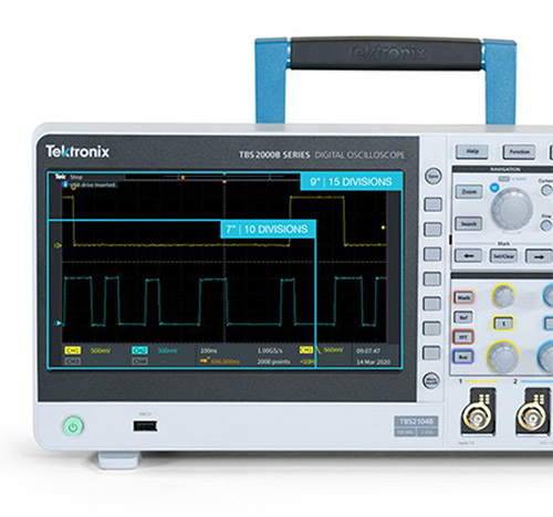
5M point record length, 200 MHz bandwidth, and 2GS/s sample rate capture and
display significantly more signal to debug and validate designs faster.
New lower noise front end design offers lower random noise, better signal
integrity and more accurate measurements.
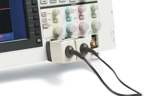
TekVPI™ probe interface supports wide range of active, differential, and
current probes with automatic scaling and units.
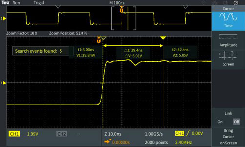
On-waveform cursor readouts with search and mark features enable easy
identification of events that occur in the acquired waveform.
Educators can disable the autoset, cursors, and automated measurements to
facilitate teaching basic concepts.
Bandwidth is field-upgradeable.
Share more, with ease.
The TBS2000B is the first oscilloscope with Wi-Fi support via a USB Wi-Fi
dongle. It also has 2 USB host ports and 100-BaseT Ethernet port, making it
easy to share measurements and collaborate—with your lab partner or across
the globe. Plus, the included software lets you easily connect to your PC to
grab screen images and analyze data.
More probes. More applications.
The TekVPI™ probe interface sets the standard for ease of use in probing. In
addition to supporting standard BNC probes, it also allows you to use the
latest-generation active voltage and current probes. TekVPI enables
communication between the TBS2000B and the latest current and differential
voltage probes, simplifying measurement setups and extending your range of
applications.
Highlights
Automatically communicate scale factors to the oscillscope.
Probe guidance such as open-jaw errors, offset settings and degauss
requirements are presented on oscilloscope display.
No external power supply is required to power the probe.
A powerful learning tool.
With the TBS2000B students can take a hands-on approach, thanks to features
that make learning engineering fundamentals easier.
HelpEverywhere offers instant tips - including measurement information,
application tips, and general guidance in the form of text and graphics
- as you navigate through key menus.
TekSmart Lab™ network software helps instructors set up and monitor many
instruments from one PC.
Courseware ecosystem lets instructors load information into the
TBS2000B, to help students during labs.
Autoset, cursors, and automated measurements can be disabled to
facilitate teaching basic concepts
Get oscilloscope waveform analysis capabilities right on your PC
Analyze waveforms anywhere, anytime with TekScope PC analysis software.
Educators and engineers alike will appreciate the ability to measure and
control waveform data from any location and share with remote colleagues and
classmates.
Recall and view waveforms, perform cursor and automated measurements,
create time trends, histograms and spectrum views for free in the base
package
Use as teaching / learning aid to for Oscilloscopes and basic signal
analysis
Perform basic instrument control, waveform transfer, analysis and
protocol decode on a TBS1000C / TBS2000B oscilloscope with
TEKSCOPE-ENTRY license
We have the only plan in the industry to offer coverage for accidental
damage. Yes, this includes screen damage, spills, broken mounts, and
electrostatic discharge or electronic overstress events. Reduce unplanned
repair or replacement costs with our Total Protection Plan. Watch the video
or click below to learn more.
The TBS2000B oscilloscope provides the embedded design engineer with a large
9-inch screen that shows 50% more horizontal signal with 15 divisions.
Easily pan and zoom through long records with front-panel waveform
navigation controls
32 automatic measurements enable you to measure the most commonly needed
parameters
Built in FFT for quick frequency domain analysis
Power Measurements
The TBS2000B offers flexible probing solutions, so you can measure a wider
range of signals without the need for a separate power supply.
Supports a wide variety of voltage and current probes with the
easy-to-use TekVPI® probe interface
Passive Probes
Current Probes
Differential Probes
High Voltage Probes
Probes automatically communicate scale factors to the oscilloscope
Active probes are powered by the oscilloscope. No external power needed
Education
The TBS2000B Oscilloscope offers new features that enable educators to devote
more time to teaching engineering concepts and less time on lab setup and
management.
Новый прибор TBS2000B специально разработан для выполнения основных задач осциллографа — отображения и
измерения параметров сигналов. Увеличенный экран осциллографа с диагональю 9 дюймов и 15 делениями по
горизонтали, а также длина записи 5nbspмлнnbspточек позволяют захватывать большие временные окна и более
тщательно рассматривать сигналы. Производительность измерений выше за счёт использования управляемых
вручную курсоров и 32 автоматических измерений. Использование порта 100-BaseT Ethernet и соединения с
сетью Wi-Fi повышает эффективность и скорость обмена данными. Это доступный по цене осциллограф с
производительностью, требуемой для решения широкого спектра задач. Посмотреть все осциллографы »
Когда лучше виден сигнал, аномалии выявляются намного быстрее. Цифровой запоминающий осциллограф
TBS2000B с уникальным, самым большим в этом классе приборов WVGA-экраном с диагональю 9 дюймов и
15 горизонтальными делениями не только увеличивает изображение, но и делает его отчётливее. Длина
записи 5 млн точек позволяет захватывать большие временные окна с более высоким временным
разрешением. Кроме того, при помощи обновлённых элементов управления сигналами на передней панели
можно легко масштабировать длинные записи.
Точные и простые автоматические измерения.
Функции цифрового запоминающего осциллографа TBS2000B удобны и просты в использовании. Новая
конструкция входов с более высокой частотой дискретизации 2 Гвыб/с обеспечивает повышение
точности измерений за счёт снижения уровня шумов и повышения эффективной разрядности. Располагая
набором из 32 автоматических измерений, можно быстро и более точно измерять самые
распространённые параметры. Для анализа сигналов можно пользоваться экранными надписями новых
курсоров, привязанных к сигналу, — почти как в учебнике.
Дальнейшее совершенствование осциллографов за счёт новых функций и опций
НОВЫЕ функции
Благодаря длине записи 5 млн точек, полосе пропускания 200 МГц и частоте дискретизации 2 Гвыб/с,
прибор захватывает и отображает намного больше информации о сигналах, что помогает ускорить
отладку и проверку проектируемых устройств.
Новые схемы малошумящих входов обеспечивают низкий уровень случайного шума, улучшение
целостности сигнала и точности измерений.
Интерфейс пробников TekVPI™ поддерживает широкий спектр активных, дифференциальных и токовых
пробников с автоматическим выбором диапазона и единиц измерения.
Экранные надписи курсоров, привязанных к сигналу, совместно с функциями установки меток и поиска
помогают быстро идентифицировать события, обнаруженные в зарегистрированном сигнале.
Преподаватели могут отключать автоматическую настройку, курсоры и автоматические измерения для
более быстрого изучения базовых положений.
Предусмотрена возможность обновления полосы пропускания в полевых условиях.
Передача данных — проще и больше.
TBS2000B — это первый осциллограф с поддержкой Wi-Fi через аппаратный ключ USB Wi-Fi. В нём также
предусмотрены 2 USB хост-порта и 1 порт 100-BaseT Ethernet, упрощающие и ускоряющие передачу
результатов измерений и совместную работу между коллегами по лаборатории, а также по всему миру.
Кроме того, входящее в объём поставки программное обеспечение позволяет быстро устанавливать
соединение с ПК для передачи экранных изображений и анализа данных.
Больше пробников. Больше вариантов применения.
Интерфейс TekVPI™ для подключения пробников — это новый стандарт простоты и удобства тестирования
при помощи пробников. Интерфейс поддерживает не только типовые пробники с разъёмами BNC, но и
активные пробники напряжения и токовые пробники последнего поколения. TekVPI обеспечивает связь
между осциллографом TBS2000B и новейшими токовыми пробниками и дифференциальными пробниками
напряжения, упрощая настройки измерений и расширяя области применения прибора.
Основные преимущества
Автоматическая передача в осциллограф коэффициентов масштабирования.
Отображение на экране осциллографа указаний по использованию пробников, таких как ошибки
закрытия клещей, настройки смещений и требования по размагничиванию сердечников.
Для подачи питания на пробники внешний источник напряжения не требуется.
Мощный инструмент обучения.
Пользуясь осциллографом TBS2000B и его функциями, упрощающими изучение основ инженерных
дисциплин, студенты могут получить практические навыки.
Режим HelpEverywhere, в котором при навигации по опциям меню на экран выводятся подсказки, в
том числе сведения об измерениях и общие инструкции в текстовом и графическом виде.
Сетевое ПО TekSmart Lab™, помогающее инструкторам настраивать и контролировать сеть приборов с
одного ПК.
Пакет программ Courseware, позволяющий инструкторам загружать информацию в TBS2000B, помогая
студентам выполнять лабораторные работы.
Возможность отключения автоматической настройки, курсоров и автоматических измерений для более
быстрого изучения базовых положений
Случается всякое! Лучше обеспечить защиту.
Компания предлагает план, покрывающий случайные повреждения, который является единственным в
отрасли. Он действительно покрывает повреждения экрана, повреждения из-за проливов, разрушение
монтажных элементов и повреждения в результате электростатического разряда или электрических
перенапряжений. Снизить незапланированные расходы на ремонт или замену поможет комплексный план
защиты. Чтобы узнать больше, посмотрите видео или нажмите на ссылку ниже.
Используя осциллографы TBS2000B при проектировании и отладке встроенных систем,
инженеры-конструкторы могут работать с большим 9-дюймовым экраном с 15 горизонтальными делениями,
на котором длина отображаемого сигнала по горизонтали в 1,5 раза больше.
Быстрое и простое масштабирование длинных записей при помощи элементов управления на передней
панели прибора
32 автоматических измерения используются для измерения самых распространённых параметров
Встроенная функция БПФ для быстрого анализа в частотном домене
Измерения характеристик силового оборудования
В осциллографе TBS2000B реализованы решения, повышающие уровень универсальности пробников и
позволяющие измерять более широкий набор сигналов без подключения к отдельному источнику питания.
Прибор поддерживает широкий спектр пробников напряжения и тока через простой в использовании
интерфейс пробников TekVPI®
Пассивные пробники
Токовые пробники
Дифференциальные пробники
Высоковольтные пробники
Пробники автоматически передают коэффициенты масштабирования в осциллограф
Питание активных пробников осуществляется от осциллографа. Внешний источник питания не
требуется
Обучение
Осциллограф TBS2000B оснащён новыми функциями, позволяющими преподавателям уделять больше времени
обучению основам инженерных дисциплин и тратить меньше времени на настройку и управление
лабораторным оборудованием.
Принадлежность, тестовая оснастка для компенсации пробников с интерфейсом
TekVPI
ПринадлежностьTEK-USB-488
Техническое описаниеОписание
КОММУНИКАЦИОННЫЙ АДАПТЕР USB — IEEE488 (GPIB) ДЛЯ ПРИБОРОВ TEKTRONIX,
СООТВЕТСТВУЮЩИХ USBTMC-USB488
ПринадлежностьTEK-USB-WIFI
Техническое описаниеОписание
Просмотр Техническое описаниеБеспроводной Wi-Fi адаптер для TBS2000, сертифицирован Федеральной комиссией по
связи США (FCC) и соответствует европейским директивам CE.
Ein DMM mit Touchscreen für Labor-/Produktionsumgebung mit mehr Messfunktionen – einschl.
Transientenerfassung, Datenvisualisierung und -analyse – zum Preis anderer 6½-stelliger
DMMs mit deutlich geringerer Leistung.
Erhalten Sie 15 integrierte Messfunktionen, einschließlich Digitalisierung,
Kapazität und Temperatur. Durchführen von Schwachstrom- und
Niedrigohm-Widerstandsmessungen an Geräten mit geringer Leistung. Erfassung von
transienten Signalen mit dem integrierten Digitalisierer. Es werden gleichzeitig
zwei Messungen angezeigt, um die Prüfdaten zu maximieren. Durch das DMM6500
entfällt der Bedarf an zusätzlichen Geräten.
Visualisierung von Daten und Identifikation von Messwertverläufen mit der
Benutzerfreundlichkeit eines Touchscreens
Sofortiger Einblick in die Messung, wie beispielsweise das Erfassen von
transienten Signalen und das Anzeigen von Datentrends und Statistiken direkt auf
dem Touchscreen, sodass Sie Ihre Daten schneller analysieren und zusätzliche
Messungen vermeiden können.
Highlights
Zeigt Diagramme von Wellenformen einschließlich Überlagerungen einer
Wellenform über einer anderen an.
Pinch- und Zoom-Funktionen ermöglichen das Untersuchen von Transienten und
Signalformen.
Cursor und Computerstatistiken dienen zur Charakterisierung von
Wellenformen.
Erweiterung auf zehn Messkanäle
Wenn Sie mehrere Geräte gleichzeitig beobachten oder Mehrpunktmessungen an einem
Gerät durchführen möchten, können Sie eine optionale Scan-Karte auswählen, die
Ihnen bis zu 10 Messkanäle zur Verfügung stellt, ohne weitere Geräte kaufen zu
müssen.
Höherer Produktionstestdurchsatz und geringere Prüfkosten
Highlights
Führt Messungen bei weniger als 0,0005 Netzzyklen oder Netzleitungen von 8,3
µs (10 µs) für 60 Hz (50 Hz) durch.
Verwendung am Gerät, intelligente Befehls- und Steuerungsverarbeitung, um
die PC-Kommunikation zu reduzieren und die Testzeit zu verkürzen.
Holen Sie sich einen umfangreichen Satz an Schnittstellenoptionen
Standard LAN LXI und USB sowie optionale GPIB-, RS-232- und
TSP-Link®-Schnittstellen
Während der Aufrüstung muss kein neuer Code geschrieben werden
Holen Sie sich die Code-Emulation für beliebte Keithley und konkurrenzfähige
DMMs, die Ihnen eine schnelle und einfache Code-Konvertierung und eine
schnellere Aufrüstung ermöglichen.
Erfassen und Analysieren von komplexen Signalformen und transienten Signalen
Das DMM6500 kann mehr als nur Messwerte auf dem Display anzeigen. Es kann auch
eine mit dem Digitalisierer aufgenommene Signalform darstellen. Über den
Touchscreen können Ausschnitte der Signalform mittels Pinch- und Zoomfunktion
erweitert werden. Zusätzlich liefern Cursor und Statistiken weitere Details zu
den Eigenschaften des Signals. Erfassen von Signalformen und Transienten mit:
1-M-Abtastung/en, 16-Bit-Digitalisierer.
Pinch- und Zoom-Manipulation eines Signals.
Statistiken, wie Mittelwert, Maximalwert, Minimalwert und Standardabweichung
der durch horizontale und vertikale Cursor definierten Signalsegmente.
Erweitern der Testkapazität durch Messung von bis zu 10 Geräten in einem
einzigen Testaufbau
Erweitern Sie das DMM6500 um eine optionale Multiplexerkarte und messen Sie an
mehreren Punkten an einem einzelnen Gerät oder führen Sie Messungen an bis zu 10
Geräten durch. Mit den Multiplexerkarten können Sie die Systemkapazität
erweitern oder zeitsparende Messungen an einem Gerät durchführen.
Highlights
Misst bis zu 10 Spannungskanäle oder 2-Leiter-Widerstand oder bis zu 5
Kanäle von 4-Leiter-Widerstand mit der optionalen 2000-SCAN-Karte.
Misst bis zu 9 Temperaturkanäle von Thermoelementen mit der optionalen
2001-TCSCAN-Multiplexerkarte. Die Karte verfügt über einen internen
Kaltstellenkompensationssensor.
Misst den Kabel- und Steckerwiderstand mit hoher Empfindlichkeit und exzellenter
Genauigkeit
Die Messung von niedrigen Widerständen erfordert gute Techniken, um thermische
Fehler und Prüfleitungswiderstände zu eliminieren. Mit dem DMM6500 können Sie
Folgendes realisieren:
Messung mit 1 µΩ Empfindlichkeit.
Verwendung der 4-Leiter-Widerstandsmessfunktion zur Vermeidung von
Messleitungsfehlern.
Verwendung der Offset-Kompensation zur Vermeidung von thermischen
Kontaktfehlern.
Maximierung des Durchsatzes bei Produktionstests
Kürzere Testzeiten durch schnellere Messungen. Es können auch bis zu 10 Geräte in
einem Prüfaufbau getestet werden. Durch die integrierte Intelligenz des DMM6500
wird die Kommunikation mit dem PC weiter minimiert. Das DMM6500 kann andere
Geräte in einem Testsystem steuern.
Highlights
Führt Messungen bei weniger als 0,0005 Netzzyklen oder Netzleitungen von 8,3
µs (10 µs) für 60 Hz (50 Hz) durch.
Verwenden Sie das interne Gerät von Keithley, den Test-Skript-Prozessors
(TSP®), zur Durchführung eines Tests und zur Steuerung anderer TSP- oder
LAN-basierter Geräte.
Verwenden Sie die optionale 10-Kanal-Scannerkarte oder die optionale
9-Kanal-Temperatur-Scannerkarte zum Testen mehrerer Geräte mit einem
Prüfaufbau.
Zubehör2000-SCAN
DatenblattBeschreibung
SCANNERPLATTE
Zubehör2001-TCSCAN
DatenblattBeschreibung
THERMOELEMENT/UNIVERSAL-SCAN-KARTE
Zubehör5805
DatenblattBeschreibung
KELVIN-TASTKÖPFE, 0,9 M (3 FUß)
Zubehör5808
DatenblattBeschreibung
KOSTENGÜNSTIGES KELVIN-TASTKOPF-SET, 1-POLIG
Zubehör7007-2
DatenblattBeschreibung
GESCHIRMTES GPIB-KABEL, 2 M (6,5 FUß)
Zubehör8501-1
DatenblattBeschreibung
TRIGGER-LINK-KABEL MIT DIN-ANSCHLUSS
Zubehör8501-2
DatenblattBeschreibung
TRIGGER-LINK-KABEL
Zubehör8503.
DatenblattBeschreibung
6-PIN-MINI-DIN-ERWEITERUNGSKABEL (M/W)
Zubehör8606
DatenblattBeschreibung
MODULARTASTKOPF-KIT
Zubehör8610
DatenblattBeschreibung
NIEDERTHERMISCHER KURZSCHLUSSSTECKER
ZubehörKPCI-488LPA
DatenblattBeschreibung
IEEE-488-SCHNITTSTELLENPLATINE MIT FLACHER BAUWEISE
ZubehörKTTI-GPIB
DatenblattBeschreibung
Anzeige DatenblattGPIB Communication and Digital I/O accessory,
user-installable
ZubehörKTTI-RS232
DatenblattBeschreibung
Anzeige DatenblattRS232 Communication and Digital I/O accessory,
user-installable
ZubehörKTTI-TSP
DatenblattBeschreibung
Anzeige DatenblattTSP-Link Communication and Digital I/O accessory,
user-installable
With a remarkably innovative pinch-swipe-zoom touchscreen user interface, the industry's largest
high-definition display, and 4, 6, or 8 FlexChannel™ inputs that let you measure one analog or
eight digital signals, the 5 Series MSO is ready for today’s toughest challenges, and
tomorrow’s too. It sets a new standard for performance, analysis, and overall user experience.
See
all oscilloscopes »
More than just a new display and user interface. A new standard.
Get the big picture and take total control, with the 15.6 HD touchscreen display. Use the
capacitive
pinch-zoom-swipe touchscreen, front panel controls, or mo="1"use to analyze and manage multiple signals
without
fighting through menus.
Available with 4, 6, or 8 FlexChannel inputs. Each can be used to look at 1 analog signal or look
at 8 digital
logic signals, just by changing the probe. Display any analog signal as a high-resolution waveform,
a spectrum,
or both at the same time, with independent acquisition controls for ea="1"ch domain.
Let no detail go unseen, with up to 16 bits of vertical resolution.
12-bit analog to digital converters deliver up to 16 bits of vertical resolution using advanced
digital signal
processing. See and measure small signal details, even if they're riding on large signals.
Buy what you need now. Add on as your needs change.
Performance
Bandwidth up to 2 GHz
Record Length up to 125 Mpoints
Digital Inputs
TLP058 Logic Probes each provide 8 digital channels
Operating System
Add Windows OS to run PC software on the scope
Signal Generation
Add a built-in Arbitrary/Function Generator
Advanced Analysis
Serial Decode/Trigger support for key buses like I2C, SPI, USB 2.0, Ethernet, CAN,
LIN, many
others
Automated compliance testing for Ethernet, USB 2.0, and Automotive Ethernet
TPP0500B (500 MHz) when you choose either the 350 or 500 MHz bandwidth option
TPP1000 (1 GHz) when you choose either the 1 or 2 GHz bandwidth option
1-year warranty on the included probes
3-year warranty on the instrument
Mouse, power cord and front cover with attached accessory pouch
Printed Installation Manual covers safety and basic operation
Comprehensive Integrated Online Help
Certificate of traceability
Accidents happen. Make sure you're protected.
We have the only plan in the industry to offer coverage for accidental damage. Yes, this includes
screen
damage, spills, broken mounts, and electrostatic discharge or electronic overstress events. Reduce
unplanned
repair or replacement costs with our Total Protection Plan. Watch the video or click below to learn
more.
Automatic serial bus decoding saves time and eliminates errors versus hand decoding. Serial bus
triggering and search enable you to isolate events for system-level troubleshooting.
Car designers rely on serial buses for error-free communications between ECUs, sensors and
actuators. They can also rely on the 5 Series MSO, equipped with CAN, CAN FD, LIN, FlexRay, and SENT
decoding and triggering to be able to get a synchronized view of their systems. The automated
Automotive Ethernet compliance suite lets you test to the standard, without becoming high speed bus
expert.
Clocks are the heart of every embedded system and digital communication link. Jitter and other
clock distortion can impact system operation, and getting to the root cause can be challenging
without the right analysis tools.
Highlights
Standard phase noise, TIE, and frequency plots and histograms
Optional advanced analysis with jitter decomposition and clock recovery
Make reliable, repeatable power quality, harmonics, switching loss, safe operating area
measurements and more with the automated power measurement and analysis package. With up to 8
high-resolution channels and a wide range of available probes, the 5 Series MSO is also ideal for
evaluating power supply sequencing, and digging into 3-phase power converters.
Today’s boards can have 20 or more power rails. Most of these are less than a few volts and have
strict noise limits. Accurate measurements demand special attention.
Highlights
Digital Power Management option automates ripple and turn-on/off measurements
Up to 8 analog input channels
Compatible low-noise TPR Series power-rail probes
Data Sheet
Software Package / Software Option
Description
Configure and Quote
Access Digital Channels
Upgrade
Description
Purchasing Details
TLP058 Logic Probe
Each probe accesses 8 digital channels on any FlexChannel for any 5 Series MSO
Whether positive or negative, your feedback helps us continually improve the Tek.com experience. Let us know if you're having trouble or if we're doing an outstanding job.
Get a complete view of your design with high-fidelity waveforms, insightful measurements, unique spectrum analysis, and flexible probing. Experience the intuitive user interface appreciated by engineers everywhere.
See signal details with high-resolution 12-bit analog-to-digital converters. Change your point of view whenever you wish with multi-channel spectrum analysis, measurement statistics, tables and trend plots.
12-bit resolution at 1.25 GHz; 16-bit resolution at 50 MHz
Results tables, measurement statistics, and trend plot views
Advanced solutions
The 5 Series adapts to suit your needs with a wide range of application-specific measurements. Add advanced analysis packages individually or install application bundles to address more diverse workloads.
Support for over 25 serial protocols covering the most common interfaces
Advanced single-phase and three-phase power analysis packages
Measurement tools for signal integrity and power integrity
Optional Windows® operating system lets you run PC software
More ways to see more signals
Versatile inputs and advanced probing technology let you see more.
Up to 8 FlexChannel™ inputs for up to 8 analog or 64 digital signals, plus an external trigger input
Includes 500 MHz or 1 GHz probes with just 3.9 pF input capacitance
TekVPI probe interface supports a wide range of active, differential, isolated and current probes
Specification Overview
Input Channels
4,6 or 8 FlexChannel inputs.
Each FlexChannel provides 1 analog signal input or 8 digital logic inputs with TLP0581 probe NEW Auxiliary trigger input
Bandwidth 1
350 MHz, 500 MHz, 1 GHz, 2 GHz
Sample Rate
6.25 GS/s
Record Length 1
Up to 500 Mpoints on all analog/digital channels
Internal Data Storage 1 NEW 250 GB removable SSD
Protocol Decode 1
Over 25 protocols available
Signal Generator 1
13 standard waveform types, plus arbitrary NEW 100 MHz maximum frequency
Digital Voltmeter 2
4 digit
Trigger Frequency Counter 2
8 digit
Display
15.6-inch (385 mm)
TFT color HD (1920 x 1080) resolution capacitive (multi-touch) touchscreen
1 - Optional and upgradeable 2 - Free with product registration
Automatic serial bus decoding saves time and eliminates errors versus hand decoding. Search functions enable you to isolate events for fast system-level troubleshooting. See the datasheet for a complete listing of more than 25 supported protocols.
Today’s boards can have 20 or more power rails. Most of these are just a few volts or less and many have strict noise limits. Make accurate multi-rail measurements with the right tools .
Highlights
Up to 8 analog input channels
Compatible with low-noise TPR Series power-rail probes
Decoding options for I2C, SPI, SMBus, SPMI and SVID
Clocks are the heart of every embedded system and digital communication link. Excessive jitter can impact system operation but the jitter analysis package will help you find the sources.
Automated compliance packages simplify testing to make sure your high-speed serial bus implementations conform to serial standards such as USB and Ethernet.
Whether your latest design uses silicon, gallium arsenide or silicon carbide, making accurate power quality, harmonics and switching loss measurements is easier with automated power measurements.
Each analog channel on the 5 Series B MSO can show you a time domain waveform, a spectrum, or both. Time and frequency plots are synchronized to help you quickly determine which signals are the victims and which ones are the aggressors.
Simplifies identifying signal integrity concerns, jitter and their related sources and provides the highest sensitivity and accuracy available for real-time oscilloscopes.
Tektronix offers a range of calibration and warranty extension plans for purchase with your instrument to protect and maintain its performance over the years. Benefits include:
OEM quality maintenance
Priority on-bench service
A host of accident protection, loaner program, and other program features
A breadth of calibration service levels and options
Invest now to avoid unplanned downtime and expense. Talk to your sales rep about adding a service plan to your instrument purchase.
Certificate of calibration and calibration label designed to meet audit requirements
Firmware updates, if applicable, along with safety and reliability updates ²
OEM procedures for measurements ²
Test data
Optional
Calibration record retention
Traceability
Uncertainty analysis
Independent verification by a ISO/IEC accredited organization (with logo on certificate)
Product/Option
Description
Tektronix Opt. C3
Calibration service 3 years. C3 provides for 2 calibration events during 3 years after shipment. Includes traceable calibration or functional verification where applicable, for recommended calibrations. Coverage includes the initial calibration plus 2-years calibration coverage.
Tektronix Opt. C5
Calibration service 5 years. C5 provides for 4 calibration events during 5 years after shipment. Includes traceable calibration or functional verification where applicable, for recommended calibrations. Coverage includes the initial calibration plus 4-years calibration coverage.
Tektronix is a leading accredited calibration services provider for all brands of electronic test and measurement equipment, servicing more than 140,000 models from 9,000 manufacturers. With 100+ labs worldwide, Tektronix serves as your single global partner delivering tailored calibration programs with OEM quality at a market price. Onsite, local pickup and delivery, and other options available.
The 5 Series MSO in an integral component in power supply measurement, design, and analysis. Whether
you are measuring switching loss and safe operating area, bode plots, power supply rejection ratios,
or in-circuit inductor and transformers and more, the 5 Series MSO is the perfect complement to your
bench. See how you can use the 5 Series MSO for today’s most popular applications, like
automated serial bus analysis and jitter analysis.
See more oscilloscope models.
More than just a new display and user interface. A new standard.
Get the big picture and take total control, with the 15.6 HD touchscreen display. Use the
capacitive
pinch-zoom-swipe touchscreen, front panel controls, or mouse to analyze and manage multiple
signals without
fighting through menus.
Available with 4, 6, or 8 FlexChannel inputs. Each can be used to look at 1 analog signal or look
at 8 digital
logic signals, just by changing the probe. Display any analog signal as a high-resolution
waveform, a spectrum,
or both at the same time, with independent acquisition controls for each domain.
Let no detail go unseen, with up to 16 bits of vertical resolution.
12-bit analog to digital converters deliver up to 16 bits of vertical resolution using advanced
digital signal
processing. See and measure small signal details, even if they're riding on large signals.
Get it done.
Add capabilities when you need them and for as long as you need them. Share data instantly in an
integrated cloud-based workspace. All to get things done, fast.
Automatic serial bus decoding saves time and eliminates errors versus hand decoding. Serial bus
triggering and search enable you to isolate events for system-level troubleshooting. See the datasheet for a complete list.
Car designers rely on serial buses for error-free communications between ECUs, sensors and
actuators. They can also rely on the 5 Series MSO, equipped with CAN, CAN FD, LIN, FlexRay, PSI5
and SENT decoding to be able to get a synchronized view of their systems. The automated Automotive
Ethernet compliance suite lets you test to the standard, without becoming a high speed bus expert.
Clocks are the heart of every embedded system and digital communication link. Jitter and other
clock distortion can impact system operation, and getting to the root cause can be challenging
without the right analysis tools.
Highlights
Standard phase noise, TIE, and frequency plots and histograms
Optional advanced analysis with jitter decomposition and clock recovery
Make reliable, repeatable power quality, harmonics, switching loss, safe operating area
measurements and more with the automated power measurement and analysis package.
Today’s boards can have 20 or more power rails. Most of these are less than a few volts and have
strict noise limits. Accurate measurements demand special attention.
Highlights
Digital Power Management option automates ripple and turn-on/off measurements
Up to 8 analog input channels
Compatible low-noise TPR Series power-rail probes
Decoding options for SVID and SPMI
3-phase Inverters, Motors and Drives
The Inverters, Motors and Drives Analysis package performs stable power measurements on 3-phase
PWM systems with ease.
Highlights
Up to 8 analog input channels
3-phase wye, delta, and single-phase wiring configurations
Simplifies identifying signal integrity concerns, jitter
and their related sources and provides the highest sensitivity and accuracy available for
real-time oscilloscopes.
Many of the features of the 5 Series MSO are field-upgradable, including bandwidth, record
length, arbitrary/function generator, logic channels, and protocol support. This fact
sheet lists all available post-purchase upgrades.
Learn about the application software bundles that are available for the 4, 5 and 6 Series
MSOs. Application bundles are a great alternative to purchasing individual software
options, especially if you plan to address diverse applications with your o …
This document describes the remote access programming commands for the MSO44, MSO46, MSO54,
MSO56, MSO58, MSO58LP, MSO64, MSO64B, MSO66B, MSO68B, and LPD64 instruments.
The printable version of the 4/5/6 Series MSO on-instrument help system provides operation,
features, and function information. This document supports firmware version V1.36.x and
above.
TekDrive is a collaborative data workspace that provides an oscilloscope-to-cloud software
solution for instant data sharing and recall on an oscilloscope, PC, phone, or tablet.
This document highlights how TekDrive helps you stay productive while w …
The Tektronix TekExpress LVDS transmitter test application offers a physical layer test
solution for transmitter parameter measurements and characterization.
This document helps customers with data security concerns to sanitize or remove memory
devices from their 6 Series B MSO instrument. The instructions also support 5 Series MSO
instruments with a serial number of B020000 and above or C040000 and above.
This document describes how to clear or sanitize 5 Series and 6 Series MSO instruments that
have option 5-SEC or 6-SEC installed, to allow removal from a secured area, or returning the
instrument for repair.
Tektronix offers a wide range of hardware and software built to help you design and test
mission-critical RF systems, such as military comms, radar and electronic warfare—from
algorithm prototyping to testing to ongoing maintenance. Our products are …
This fact sheet compares important specifications and features of the Tektronix 5 Series MSO
Mixed Signal Oscilloscope to those of the Yokogawa DLM4000 Series
This fact sheet compares important specifications and features of the Tektronix 5 Series MSO
Mixed Signal Oscilloscope to those of the Keysight S-Series
This primer provides an overview of the trends, challenges and solutions associated with the
expected future evolution of in-vehicle networks, as well as a foundation for testing
in-vehicle networks to accelerate new designs to production, streamline …
Visual triggers let you capture waveforms of interest by drawing trigger areas on an
oscilloscope display. Start by learning how to trigger on bursts of specific length,
then move on to pulse trains and more complex signals.
This application note describes how the high bandwidth, low capacitance passive voltage
Tektronix probes bridge the gap between general purpose passive probes and higher cost
active probes.
SENT bus is used in automotive sensors to transmit measurements to electronic control units.
This application note gives a brief orientation on SENT and explains how to set up decoding
and triggering on a 5 Series MSO oscilloscope equipped with SENT …
Mixed signal oscilloscopes (MSOs) are able to capture both analog and digital
representations of signals, making them well-suited for identifying problems with setup and
hold times. Learn how to use the digital capture functions of an MSO, as well a …
Timing jitter is the unwelcome companion of all electrical systems that use voltage
transitions to represent timing information. This paper focuses primarily on jitter in
electrical systems.
This fact sheet compares important specifications and features of the Tektronix 5 Series MSO
Mixed Signal Oscilloscope to those of the Rohde & Schwarz RTO2000 Series
This fact sheet compares important specifications and features of the Tektronix 5 Series MSO
Mixed Signal Oscilloscope to those of the Keysight X6000 Series
Measurement resolution depends on more than the number of bits coming out of an
oscilloscope's ADC. You need to have a whole-system, end-to-end approach to limit the
effects of noise, as well as improve resolution. Learn measurement and signal-proces …
Learn the basics of the 10BASE-T and 100BASE-TX Ethernet physical layers to help you
troubleshoot bus problems or related system issues. Learn how to set up and interpret the
results when using automated decoding, triggering, and search on an oscillo …
Explains the physical layer basics of CAN, LIN, and FlexRay serial buses to troubleshoot bus
problems or system issues. Learn how to use automated decoding, triggering, and search on an
oscilloscope equipped with automotive bus analysis capability.
Get a brief orientation on the physical layer and packet structures of SPMI power management
bus and learn how to set up decoding, triggering, and searching on an oscilloscope equipped
with SPMI decoding.
Learn the basics of the hardware protocols of the most common serial buses. Find out how to
use the protocol trigger, decode and search capabilities of oscilloscopes to solve serial
bus integration and debug challenges.
Troubleshooting embedded systems often demands more than the 2 or 4 measurement channels
available on most oscilloscopes. Using a mixed signal oscilloscope and clever
application of digital channels can provide much broader system visibility. This …
This fact sheet compares important specifications and features of the Tektronix 5 Series MSO
Mixed Signal Oscilloscope to those of the LeCroy HDO9000 Series
This fact sheet compares important specifications and features of the Tektronix 5 Series MSO
Mixed Signal Oscilloscope to those of the LeCroy HDO6000A Series and HDO8000A Series
As the move toward Automotive Ethernet technology in vehicles accelerates, comprehensive
design validation is vital to ensure interoperability and reliable operation across multiple
ECUs. This application note provides information on Automotive Ether …
Learn how to measure current using shunt resistors and voltage probes, and how to use
clamp-on current probes with your oscilloscope. Get tips on improving the resolution of your
current measurements and avoiding common pitfalls.
Learn the basics of the USB 2.0 physical layer to troubleshoot bus problems or system
issues. Learn how to set up and interpret the results when using automated decoding,
triggering, and search on an oscilloscope equipped with USB 2.0 bus analysis c …
After reading this primer, you will be able to: Describe how oscilloscopes work, Describe
the differences between analog, digital storage, digital phosphor, and digital sampling
oscilloscopes, describe electrical waveform types, understand basic osci …
Learn how to use FastFrame segmented memory on the 4, 5, and 6 Series MSOs to capture
more critical signal information by capturing important bursts and ignoring deadtime
This application note explains probing techniques for making high-quality measurements on
power supplies. It covers the use of passive and differential probes with emphasis on
applications in power conversion circuits.
Shows how to perform quick checks on an Analog to Digital Converter (ADC) gain, offset and
linearity, using a function generator and mixed signal oscilloscope (MSO). The MSO is
used to uncover a problem with offset error.
The Tek049 ASIC is the powerhouse behind Tek’s new 5 Series MSO, and it will power
next-generation oscilloscopes. This paper examines some of the technology and innovations in
this new mixed-signal ASIC.
Learn about the physical layers of the most common interchip buses - I2C and SPI - to enable
you to troubleshoot bus problems or system issues. Learn how to set up and interpret
the results when you use automated decoding, triggering, and search on …
This document describes how the Tektronix Control Loop Analysis Kit provides a simple test
setup for validating and debugging feedback loop stability. This setup
also enables engineers to test power supply rejection ratio (PSRR) on the regulator sta
…
The 3 Series MDO and 4, 5 and 6 Series MSOs offer the largest displays and the
greatest user experience of any oscilloscope. This brochure gives an overview of the
platforms, with the similarities and differences between the four series.
Learn how modern oscilloscopes can be used to build Bode plots for frequency response
analysis, determine gain and phase margins, and evaluate power supply designs for
stability.
Provides in-depth information on how to use the SignalVu-PC Vector Signal Analysis Software.
This PDF version of the Help contains the most complete descriptions of how to use the base
software and all of its optional applications.
This is a version of the 4/5/6 Series MSO (MSO44. MSO46, MSO54, MSO56, MSO58, MSO58LP,
MSO64, LPD64, MSO64B, MSO66B, MSO68B) on-instrument help system. Supports firmware version
V1.32.x.
Magway, an innovative start-up in London, is developing a new rail-based parcel delivery
system with the help of advanced DQ axis analysis from Tektronix with the 5 Series
MSO Mixed Signal Oscilloscope and current (TCP0030A) and differential voltage …
The procedure for recovering a Windows system image on a 5 or 6 Series MSO is outlined in
the section labeled “Restoring a Windows SSD” in the “Option SUP5-WIN, SUP6-WIN, SUP6B-WIN,
SUP6B-LNX Upgrade Kit Installation Instructions”. This document can …
Tektronix offers a range of efficient and intuitive remote education solutions that combine
with our oscilloscopes, DMMs, data acquisition systems, or other tools to help students put
engineering theory into practice. Read this flyer to learn how ou …
This document contains operation information for the TekExpress Ethernet Tx Compliance
Solution. It is a PDF version of the help system accessible in the TekExpress software.
Bode plots using built-in digital downconverters (Spectrum View) can provide better
resolution than traditional FFTs. Demonstrated on two different devices under test.
The Tektronix USB2.0 compliance test application (Opt. 5-CMUSB2, Opt. 6-CMUSB2) running on a
5 Series MSO and 6 Series MSO oscilloscope provides a one-button compliance testing for
USB2.0 devices, hosts, and hubs. The USB software automates the compl …
Explains the Programming Interface Command Translator which enables state-of-the-art
oscilloscopes to interpret commands for older oscilloscopes, facilitating the replacement of
older oscilloscopes in automated systems without changing commands.
Tektronix TekExpress Automotive Ethernet solution provides automated compliance test support
for 100Base-T1 (IEEE Std.802.3bw), 1000Base-T1 (IEEE Std 802.3bp™-2016) standard and Open
Alliance TC8 ECU specification for PMA Transmitter electrical speci …
This is a printable version of the 4/5/6 Series MSO (MSO44. MSO46, MSO54, MSO56, MSO58,
MSO58LP, MSO64, LPD64) on-instrument help system. Supports firmware version V1.32.x.
Learn how to simulate sensor and bus signals on an arbitrary waveform generator. Find
out how to capture signals using an oscilloscope, edit them using PC software, and play them
back on an arbitrary/function generator.
This document describes the remote access programming commands for the MSO44, MSO46, MSO54,
MSO56, MSO58, MSO58LP, MSO64, MSO64B, MSO66B, MSO68B, and LPD64 instruments.
TekExpress Industrial Ethernet Compliance SolutionThe TekExpress Industrial Ethernet
application (10Base-T1L) is a compliance test solution for performing transmitter electrical
specification measurements and MDI return loss measurements in accordanc …
Tektronix TekExpress Automotive Ethernet solution provides automated compliance test support
for 100Base-T1 (IEEE Std.802.3bw), 1000Base-T1 (IEEE Std 802.3bp™-2016) standard and Open
Alliance TC8 ECU specification for PMA Transmitter electrical speci …
The Tektronix TekExpress LVDS transmitter test application offers a physical layer test
solution for transmitter parameter measurements and characterization.
Learn how to use near-field probes and spectrum analysis on 4, 5 and 6 Series MSOs to look
for potential sources of self-interference, especially on the compact wireless IoT devices.
This application note will help designers verify the shape of current pulses from
electrostatic discharge (ESD) simulators prior to compliance or pre-compliance
testing.
With TekExpress Ethernet Compliance Test Software, engineers validating an Ethernet physical
layer can perform reliable compliance tests of 10Base-T, 100Base-TX, 1000Base-T and
1000Base-T Multipair technologies in their labs. This application enhanc …
Tektronix probes ensure the highest signal fidelity possible from your device-under-test to
your oscilloscope. With over 100 probe choices available, all perfectly matched to our
industry-leading oscilloscopes, you can find the probe you need for you …
This document describes the remote access programming commands for the MSO44, MSO46, MSO54,
MSO56, MSO58, MSO58LP, MSO64, MSO64B, MSO66B, MSO68B, and LPD64 instruments. Supports
firmware version 1.26 and above.
With today’s rapid advances in radar technology, developing and manufacturing highly
specialized and innovative electronic products to detect radar signals takes leading-edge
technology and tools. Tektronix innovative test equipment reduces testingun …
Read this case study to learn how the Motor Drives and Power Electronics Lab (MPlab) at
Columbia University’s Electrical Engineering used an MSO58 8-channel oscilloscope to analyze
three-phase motor drives and multi-phase power electronics systems to …
Refer to the Prerequisites.txt file available to download on the same page for
OpenChoice desktop. Make sure you have all the prerequisites specified.
Prerequisites
1. PC equipped with Microsoft Windows 7 32 Bit and 64 Bit OS, Windows 8.1 32 Bit …
TekSeriesScope IVI-COM Driver for 4, 5, 6 and 6B Series Mixed Signal Oscilloscopes; 5 and 6
Series Low Profile Digitizers IVI Scope class-compliant driver. It complies with Scope Class
specifications (IVI-4.1) as defined by the IVI foundation. An IVI …
Students at The University of Naples are now able to focus more attention on the experiment
at hand, rather than worrying about the tool being used to monitor it. Read this case
study to learn how.
You’ll learn the basics of checking the power-on and power-off sequence of an AC-DC power
supply, how to look at a bulk supply and various point of load regulators, and how an
oscilloscope with more than 4 channels can expedite the process.
Learn about the connection between signal integrity on data and clock lines, and power
integrity. Includes a review of jitter measurements and types of power rail noise that
cause jitter.
This white paper describes an approach in which new oscilloscope ADC technology, combined
with digital signal processing and a low-noise front end, can provide even higher resolution
than found in conventional high bit-rate ADC implementations. It di …
SignalVu-PC VSA software brings the analysis engine of the Tektronix Real-Time Signal
Analyzer (RTSA) to your computer, enabling you to analyze live signals from RSA306, RSA500,
RSA600, RSA7100A\B Spectrum Analyzers, MSO54, MSO56, MSO58, MSO64, MDO40 …
Chalmers Formula Student is a team of 33 engineering students in Sweden who were designing
and building an electric, all-wheel drive race car to compete against other engineering
students. Chalmers Formula Student partnered with Tektronix who provid …
This document describes how to install SignalVu-PC, how to activate SignalVu-PC, how to
connect to an instrument with SignalVu-PC, and provides a brief introduction to the
application. SignalVu-PC can be used with the RSA306B, RSA500 Series, RSA600 Series, RSA7100
Series, MDO4000B/C, and MSO5/6 Series.
Tektronix TekExpress Automotive Ethernet solution provides automated compliance test support
for 100Base-T1 (IEEE Std.802.3bw), 1000Base-T1 (IEEE Std 802.3bp™-2016) standard and Open
Alliance TC8 ECU specification for PMA Transmitter electrical speci …
No, but there is no need to. The Windows build on Tektronix scopes is from the
Long-Term Servicing Channel (Windows 10 Enterprise LTSC).
Unlike normal releases of version 1607, this release still receives security updates and
support from Microsoft, …
The visual trigger option is not listed in the trigger type selection
initially. To setup the visual trigger, simply click on the "DRAW A
BOX" icon (located in the lower right corner of the display) to draw the areas for
the visual trigger. After t …
It is in the “Acquisition” badge located in the lower right corner of the screen. It allows
the user to set the configuration to save the waveform file or screen capture when there is
a triggered event.
Currently, there is no auto measurement for the positive or negative pulse count on the 5/6
Series MSO.
The workaround would be using the “Search” feature to search for the pulse width.
First, set up for the positive pulse width auto measurement fo …
The Windows build on Tektronix scopes is from the Long-Term Servicing Channel (LTSC),
specifically Windows 10 Enterprise 2016 LTSB (Long-Term Service Branch 1607). You can
read more about the LTSC here: https://docs.microsoft.com/en-us/windows/whats …
Both 5 and 6 series MSO support a deskew range of -125ns to +125ns.
The 6 series MSO can be adjusted in 1ps resolution for all acquisition modes except Peak
Detect and Envelope (40ps resolution).
The 5 series MSO can be adjusted in 40ps resolution fo …
Since its invention by Tektronix in the 1940s, the oscilloscope’s trigger system has been a
key component of the products, providing a stable display of repetitive signals and the
capture of specific events in a signal. At the circuit level, the trig …
The Floating Licenses are good forever; however, the checkout of the Floating License
is good for for any duration from 4 hours up to 4 years, selectable at the time of
check out. After it reaches selected duration, it will automatically check itsel
…
For our Linux based instruments or programs licensed under the “GNU General Public License
(GPL) or Lesser GNU General Public License (LGPL)” the complete corresponding sources are
available. You can order a complete machine-readable copy of the sour …
Yes. To setup a peer to peer connection, you must manually configure the IP and subnet mask
address on both the scope and your computer. You can then use an ethernet cable connected
directly between the scope and computer. This will work on the Linu …
Screenshots (also known as hard copies) can be transferred from the Series 4, 5 and 6 MSO
oscilloscopes via the remote programming interface using just a few simple commands.
For information on how to send commands to the instrument via the remote p …
Each analog channel on the 5 and 6 Series MSO can be converted into 8 digital channels
with the logic probe TLP058.
For a 4-channel model (MSO54, MSO64), it is up to 32 digital channels.
For a 6-channel model (MSO56), it is up to 48 digital channels …
The .wfm waveform files saved from Tektronix DPO/DSA/MSO 5K 7K 70K and 5 and 6 Series MSO
oscilloscopes contains a time stamp that indicates the time that the scope was triggered.
This example program shows how you can extract this time stamp from th …
Introduction
Network drives were introduced in firmware version 1.8.7 for 5 Series, 5 Series Low Profile,
and 6 Series MSOs. This feature allows you to specify a directory on another computer
for the scope to use as storage. To access this storage, …
Updating Windows 10 Using Windows Update
By default, Windows 10 will attempt to automatically keep itself up to date with the latest
critical security patches, but it will not install optional updates. To ensure Windows
10 receives all available upd …
After you have registered your oscilloscope on Tek.com, you should have received an email
with instructions. The email is sent to the address you used to login to
tek.com. If you haven't received the email after registration:
Check your spam folde …
On firmware v1.12 or above, the 5/6 Series MSO added the stacked and overlay mode mix and
match feature. It allows user to group multiple channels for overlay mode for easy
comparison.
To separate the channels in the group, there are couple options …
There are three indicators to look for. A Windows scope will have the Applications menu at
the top center of the screen and minimize/maximize/close buttons on the top right. In
addition, if you tap at the bottom of the screen, the Windows Taskbar sho …
With firmware v1.16, the invert function is available in the channel menu.
If the unit has the older firmware v1.14 or below, the invert channel feature on the 5
or 6 series MSO is supported via the math channel instead.
Here is the setup procedure: …
Instruments that have both a Linux drive and a Windows drive should have the same firmware
revision on both drives.
When only one drive has the latest firmware installed, the instrument user may find that
firmware is not updated on the Linux drive o …
Yes. With firmware v1.8 or above, using the web browser access to the
Windows 10 version is supported along with TightVNC. TightVNC must be
installed on both the remote PC and the scope. For the detailed setup
instructions, please see the 5/6 seri …
Yes! Tektronix offers many different models of real-time oscilloscopes that provide 12-bit
or greater vertical resolution for a variety of applications.
Because many high-vertical-resolution oscilloscopes on the market have technical trade-offs
such …
To answer this first you need to understand the layout of how your waveform trace is
displayed.
On your oscilloscope you generally will see either 8 or 10 divisions vertically on the
screen.
Along the left side of the screen you will see a marker …
Yes. However, it does not apply to both events. It could be only either A or B event for
the bus trigger. The second event is locked to edge trigger type.
This document covers the basics of oscilloscopes including history and general
operation, in this training presentation developed by a Tektronix Applications Engineer.
Learn the XYZ's of Oscilloscopes »
AFG in MDO3000, MDO4000C, and 5 Series MSO do not have sweep function. But a limited sweep
may be created using the arbitrary function.
Example: Create a sweep from 100 KHz to 250 KHz.
ArbExpress (free software on Tek.com) select Equation Editor an …
Most field upgrades for the optional features for the 5 Series MSO are also available for a
one-time, 30-day free trial. These are available simply by requesting a trial software
license and installing the node-locked license in the instrument.
Ther …
The 5 and 6 Series MSO setup files contain all instrument settings, user-configured
analysis, and reference waveforms, so they provide an easy way to return the oscilloscope to
a known state. For example, if you want to build a library of standardize …
When you purchase a 5 Series MSO with the 5-WIN option or a 6 Series MSO with the 6-WIN
option installed, or upgrade your 5 Series MSO with the SUP5-WIN upgrade, or upgrade your 6
Series MSO with the SUP6-WIN upgrade, you will see very few difference …
Roll Mode provides an instant display response when the oscilloscope is operating at very
slow sweep speeds. Without it, the acquisition must complete before the display will update.
With Horizontal Scale factors as slow as 1000 s/div, that can be a …
The 5 and 6 Series MSO will display a pop-up warning message when it is not completely
successful recalling the saved state of the instrument with a setup or session file.
The following message will appear on the display:
WARNING
The oscilloscope …
Yes, the 5 and 6 Series MSO hardware supports a total of three displays, including the
instrument’s internal display. The instrument provides DVI-D, Display Port, and VGA
connectors on the rear panel.
The standard instrument (running the Linux operat …
After you place an order for the software license or an upgrade for your 5 or 6 Series MSO,
you will receive an email (at the email address in your MyTek account). It will look about
like this, but customized for you:
Dear Customer (customer@custome …
Most optional, factory-installed features for the 5 Series MSO are also available as field
upgrades, and are installed simply by ordering an upgrade product and entering a new,
node-locked software license into the instrument.
There are several gene …
Bandwidth upgrades to 500 MHz and 1 GHz can be accomplished by ordering an upgrade product
and entering a new software license into the instrument. The instrument bandwidth appears in
the Help-> About menu near the top of the window, between the Mode …
For the standard instrument (without the Windows 10 option installed), you can simply
connect your computer to the instrument through Ethernet and control the oscilloscope with
your favorite browser.
Find the instrument’s IP address by selecting Uti …
The oscilloscope has a built-in m.2 drive, labeled C:. This drive can be used to store
waveforms, setups, and measurement results. However, this drive is not easily accessible to
your computer.
The oscilloscope also has several USB ports to support …
Oscilloscope probes which contain active circuitry, especially with amplifiers in the signal
path, have a limited dynamic range over which the probe behaves linearly. When input signals
exceed this range, the signal may be distorted. (Such probes als …
Get a quick review of inductor and transformer theory, and learn how to use an oscilloscope
with power analysis software to perform dynamic inductance measurements under operating
conditions.
Learn how to work remotely from your oscilloscope by exporting data, offline analysis, using
PC software, custom programming and Windows Remote Desktop. This brief covers oscilloscopes
that run the Windows operating system.
Learn how to work remotely from your oscilloscope by exporting data, offline analysis, using
PC software, custom programming and remote access over a LAN. This brief covers
oscilloscopes that do not run the Windows operating system.
With TekExpress Ethernet Compliance Test Software, engineers validating an Ethernet physical
layer can perform reliable compliance tests of 10Base-T, 100Base-TX, 1000Base-T and
1000Base-T Multipair technologies in their labs. This application enhanc …
This application note describes techniques using an oscilloscope that can help you determine
the source of unwanted radiated emissions (EMI), especially after an out-of-limits condition
has been identified through formal testing or pre-compliance tes …
Tektronix oscilloscopes offer a portfolio of optional analysis capabilities to simplify
serial bus debug or compliance verification. This selection matrix shows which serial
standards are supported by each of the oscilloscope series.
Automotive Ethernet operates as a full-duplex communication link over a twisted-pair cable.
The Full-Duplex communication, along with PAM3 signaling, adds complexity in validating the
Electronic Control Units (ECU) in real-world conditions. The TekExpress Automotive PAM3
Analysis application includes unique Signal Separation capability and Electrical analysis.
Spectrum View is a new way of performing spectrum analysis on an oscilloscope. This
application note shows and explains how Spectrum View operates and how it differs from
traditional oscilloscope FFT functions.
This application note explains how to set up an oscilloscope to take these measurements with
4-PWR-BAS, 5-PWR and 6-PWR analysis software. It gives a high-level overview of the
various measurements, including power quality, switching loss, and ripple …
The Tektronix TekExpress Automotive PAM3 Analysis is an automated test solution for
performing Signal Separation on a Full duplex of 100BASE-T1 and 1000BASE-T1 Automotive
Ethernet signals at system level.User can use this application to perform Signa …
Download this firmware to install the latest updates for the 5 Series MSO. This firmware
only applies to oscilloscopes that do have option 5-WIN (Windows 10) installed.
Download this firmware to install the latest updates for the 5 Series MSO. This firmware
only applies to oscilloscopes that do not have option 5-WIN (Windows 10) installed.
The MIPI I3C standard defines a two-wire interface with a bidirectional data bus for
connecting sensors to an application processor. This application note gives a brief
orientation on the physical layer and packet structures of the I3C protocol. It …
This document contains operation information for the TekExpress Automotive Ethernet
(10Base-T1S) Compliance Analysis Solution. It is a PDF version of the help system accessible
in the TekExpress software.
Tektronix TekExpress Automotive Ethernet solution provides automated compliance test support
for 10BASE-T1S (IEEE Std 802.3cg) standard, 100BASE-T1 (IEEE Std.802.3bw) and 1000BASE-T1
(IEEE Std 802.3bp™-2016) standard for Transmitter electrical test …
Download this firmware to install the latest updates for the 5 Series MSO oscilloscopes.
This firmware only applies to oscilloscopes that have option 5-WIN (Windows 10) installed.
Download this firmware to install the latest updates for the 5 series MSO oscilloscopes.
This firmware only applies to oscilloscopes that do not have option 5-WIN (Windows 10)
installed.
12-bit analog-to-digital converters deliver higher resolution on the 4, 5 and 6 Series MSO
oscilloscopes
Higher resolution oscilloscope measurements are becoming more important given today’s signal
levels. Scopes are available with 12-bit analog-to- …
Tektronix TekExpress Automotive Ethernet solution provides automated compliance test support
for 100Base-T1 (IEEE Std.802.3bw) and 1000Base-T1 (IEEE Std 802.3bp™-2016) standard for
Transmitter electrical test specification as per Open Alliance. The …
Download this firmware to install the latest updates for the 5 Series MSO oscilloscopes.
This firmware only applies to oscilloscopes that have option 5-WIN (Windows 10) installed.
Download this firmware to install the latest updates for the 5 series MSO oscilloscopes.
This firmware only applies to oscilloscopes that do not have option 5-WIN (Windows 10)
installed.
The application provides more visibility into your Ethernet designs with
1000BASE-T/100BASE-TX/10BASE-T PHY measurements as outlined in IEEE 802.3 Section 40, ANSI
X3.263, and IEEE 802.3 Section 14 specific measurements for different Ethernet standards to
the already existing rich tool set of generic jitter, timing, and signal quality
measurements in Tektronix Oscilloscope.
Ethernet compliance testing requires precise test setups and evaluation against limits
dictated by IEEE 802.3 standards. Automated testing software for oscilloscopes greatly
simplifies and speeds testing. This application note summarizes key tests …
With TekExpress Ethernet Compliance Test Software, engineers validating an Ethernet physical
layer can perform reliable compliance tests of 10Base-T, 100Base-TX and 1000Base-T
technologies in their labs. This application enhances efficiency with fast …
TekSeriesScope IVI-COM Driver for 4, 5 and 6 Series Mixed Signal Oscilloscopes; 5 and 6
Series Low Profile Digitizers IVI Scope class-compliant driver. It complies with Scope Class
specifications (IVI-4.1) as defined by the IVI foundation. An IVI cla …
The Tektronix TekExpress LVDS transmitter test application offers a physical layer test
solution for transmitter parameter measurements and characterization.
This application note explains how to measure switching loss and conduction loss in power
supply switches using an oscilloscope equipped with a current probe and differential voltage
probe. It covers both manual and automated techniques, along with p …
TekVISA is the Tektronix implementation of VISA (Virtual Instrument Software Architecture),
an industry-standard communication protocol.When installed on a PC, TekVISA provides
communication with instruments that are connected to the PC via various c …
TekExpress Industrial Ethernet Compliance Solution - MSO 5000 and 6000The TekExpress
Industrial Ethernet application (10Base-T1L) is a compliance test solution for performing
transmitter electrical specification measurements and MDI return loss measu …
This document contains operation information for the TekExpress Industrial Ethernet
Compliance Solution. It is a PDF version of the help system accessible in the TekExpress
software.
Gives examples of jitter analysis, from basic analysis to more advanced jitter decomposition
techniques using the 5 Series Mixed Signal Oscilloscope on unmodulated clocks, spread
spectrum clocks, and serial data.
The Tektronix TekExpress Automotive PAM3 Analysis is an automated test solution for
performing Signal Separation on a Full duplex 100BASE-T1 Automotive Ethernet signals at
system level. User can perform measurements like eye height and eye width can …
The TekSeriesScope IVI-COM Driver for 4, 5 and 6 Series Mixed Signal Oscilloscopes is an IVI
Scope class-compliant driver. It complies with Scope Class specifications (IVI-4.1) as
defined by the IVI foundation. An IVI class-compliant specific driver …
Download this firmware to install the latest updates for the 5 series MSO oscilloscopes.
This firmware only applies to oscilloscopes that do not have option 5-WIN (Windows 10)
installed.
Tektronix TekExpress Automotive Ethernet solution provides automated compliance test support
for 100Base-T1 (IEEE Std.802.3bw) and 1000Base-T1 (IEEE Std 802.3bp?-2016) standard for
Transmitter electrical test specification as per Open Alliance. The …
Download this firmware to install the latest updates for the 5 series MSO oscilloscopes.
This firmware only applies to oscilloscopes that do not have option 5-WIN (Windows 10)
installed.
The Tektronix TekExpress Automotive Ethernet solution provides automated compliance test
support for 100Base-T1 (IEEE Std.802.3bw) and 1000Base-T1 (IEEE Std 802.3bp™-2016) standard
for Transmitter electrical test specification as per Open Alliance. T …
The Tektronix USB2.0 compliance test application (Opt. 5-CMUSB2, Opt. 6-CMUSB2) running on a
5 Series MSO and 6 Series MSO oscilloscope provides a one-button compliance testing for
USB2.0 devices, hosts, and hubs. The USB software automates the compl …
This application note provided an overview of USB 2.0 physical layer testing including
signal quality, in-rush current check, drop and droop tests, as well as tests for high-speed
mode.
This document describes the operation of the Tektronix Demo 3 Board. The Demo 3 board
provides signals to demonstrate key Tektronix instrument features.
Whether positive or negative, your feedback helps us continually improve the
Tek.com experience. Let us know if you're having trouble or if we're doing an outstanding job.
With the largest display and highest available channel count in its class, the 4 Series offers
unprecedented insight in a bench-friendly package. And its made-for-touch user interface works
exactly as you'd expect.
Watch how the 4 Series MSO user interface helps you work better and faster.
Biggest display in its class and award-winning user interface
With the same made-for-touch user interface technology as the award-winning 5 Series and the
largest and highest resolution display in its class, the 4 Series MSO sets a new expectation of
how a scope should work.
13.3-inch HD display
6.1-inch (15.5 cm) deep bench-friendly footprint
Outstanding details and up to 6 super-flexible channels
Any channel can show a waveform, spectrum, or both
Any input can be used to view eight digital channels by connecting a logic probe
Outstanding detail and accurate measurements on all channels
12-bit vertical resolution (16-bit in high res mode)
6.25 GS/s on all analog and digital channels
Up to 62.5 Mpoints record length
Watch and learn how 4 Series performance helps you see more.
Specs at a glance
Input Channels
4 or 6 FlexChannel inputs
Each FlexChannel provides 1 analog signal input or 8 digital logic inputs with TLP058 probe
1 - Optional and upgradeable 2 - Free with product registration 3 - Partial list of decode and analysis options. See datasheet for all supported buses.
Signal
Generation1
Arbitrary, Sine, Square, Pulse, Ramp, Triangle, DC Level, Gaussian, Lorentz, Exponential
Rise/Fall, Sin(x)/x, Random Noise, Haversine, Cardiac
Digital
Voltmeter2
4-digit AC RMS, DC
DC+AC RMS voltage
Trigger Frequency
Counter2
8-digit
Advanced Analysis
Spectrum View Mixed Domain Analysis
Automated Power Measurements1
3-Phase Power Measurements1
Protocol
Support3
10BASE-T, 100BASE-TX
CAN, CAN FD, LIN, FlexRay
I2C, SPI
MIL-STD-1553, ARINC 429
RS-232, RS-422, RS-485, UART
SPMI
SVID
USB 2.0 LS, FS, HS
Display
13.3-inch (338 mm)
HD color (1920 x 1080) capacitive touchscreen
Dimensions (H x W x
D)
287 mm x 405 mm x 155 mm
(11.3 in x 15.9 in x 6.1 in)
Weight
16 lbs (7.3 kg)
Included probes and
accessories 1 - Optional and upgradeable 2 - Free with product registration 3 - Partial list of decode and analysis options. See datasheet for all supported buses.
September 2023 firmware release enables these new features and options
Upgrades on all instruments
New measurement annotations display reference levels, top/base levels, start/end points and more
New trace file records commands sent to the programming interface
Upgrades on instruments with advanced analysis options
Accurate measurements start with great probes. Every 4 Series comes with the best passive
probes in the industry, with loading of just 3.9 pF and up to 1 GHz bandwidth. The TPP Series
probes will be your go-to probes for everyday use.
Highlights
TPP Series probes included standard. One per analog channel.
Industry-best capacitive probe loading of 3.9 pF
250 MHz, 500 MHz or 1 GHz probe bandwidth depending on instrument bandwidth
See the capability the 4 Series MSO can bring to your bench.
See the full line of next-generation
oscilloscopes
Whether you’re debugging serial buses or designing to
high speed digital standards, we’ve set a new standard in scope user interface so you can get to your
answers faster and easier.
Serial bus decode and trigger options transform the 4 Series MSO into an indispensable tool for
debugging serial buses with automatic decode, trigger, and search. Here are a few examples:
Even with lower standby power, faster switching and stricter noise limits, the 4 Series can
speed up power supply troubleshooting, optimization and validation.
AC line and harmonics measurements
Switching loss analysis
DC power rails measurements
Bode plots and power supply rejection ratio
Wide range of current, power rail, differential, and optically-isolated probes
With the Spectrum View option each analog channel on the 4 Series MSO can show you a time
domain waveform, a spectrum, or both. The time and frequency plots are synchronized to help you
quickly determine which signals are the victims and which ones are the aggressors.
Загрузить руководства, технические описания, программное обеспечение и т. д.:
Обратная связь
Хотите предоставить отзыв? Мы будем рады услышать ваше мнение.
Ваши отзывы, как положительные, так и отрицательные, помогают нам постоянно совершенствовать веб-сайт Tek.com. Сообщайте нам, когда сталкиваетесь с проблемами или если считаете нашу работу важной и полезной.
Осциллограф Серии 4 с самым большим числом каналов и экраном среди устройств такого класса — это прибор с уникальным набором функций и характеристик, специально разработанный для настольных испытаний. Надёжность и простоту эксплуатации осциллографа обеспечивает интерфейс пользователя с сенсорным управлением.
Посмотреть больше моделей осциллографов.
Узнайте, как интерфейс пользователя MSO Серии 4 способствует повышению эффективности и скорости работ.
Инновационный интерфейс пользователя и наибольший экран среди приборов такого класса
Осциллограф MSO Серии 4, оснащённый таким же пользовательским интерфейсом с сенсорным управлением, как у новейших приборов Серии 5, а также наибольшим экраном с самой высокой чёткостью среди приборов такого класса, — это шаг на опережение в стандартах работы осциллографов.
Экран высокой чёткости с диагональю 13,3 дюйма
Удобный для настольного тестирования корпус глубиной 15,5 см
Высокая детализация сигналов и до 6 переключаемых каналов
Для каждого канала можно вывести изображение сигнала, спектра либо обе панели
Каждый вход можно использовать для просмотра сигналов, поступающих через подключённый логический пробник по восьми цифровым каналам
Высокая точность измерений и детализация сигналов на всех каналах
Разрешение по вертикали 12 бит (до 16 бит в режиме высокого разрешения)
6,25 Гвыб/с на всех аналоговых и цифровых каналах
Длина записи до 62,5 млн точек
Высокая степень детализации сигналов при тестировании осциллографом Серии 4
Общие технические характеристики
Число входных каналов
4 или 6 входов FlexChannel
На каждый вход FlexChannel через пробник TLP058 может поступать 1 аналоговый или 8 цифровых логических сигналов
Полоса пропускания1
200 МГц, 350 МГц, 500 МГц, 1 ГГц или 1,5 ГГц
Частота дискретизации
6,25 Гвыб/с на всех аналоговых/цифровых каналах
Длина записи
31,25 или 62,5 млн точек
Разрешение по вертикали
12 бит
До 16 бит в режиме высокого разрешения
Пробники и принадлежности, входящие в комплект поставки 1 — Выбор опции с возможностью обновления 2 — Предоставляется бесплатно при регистрации прибора 3 — Приведён неполный список опций декодирования и анализа. Перечень всех поддерживаемых шин см. в техническом описании.
Генерируемые сигналы1
Сигналы произвольной формы, синусоидальные, прямоугольные, импульсные, пилообразные, треугольные, уровня постоянного тока, функция Гаусса, функция Лоренца, экспоненциальное нарастание/спад, кардинальный синус Sin(x)/x, белый шум, гаверсинус, кардиосигналы
Цифровой вольтметр2
Измерения ср. кв. перем. напряжения, а также пост. напряжения с разрешением 4 разряда
Измерения характеристик 3-фазных источников питания1
Поддержка протоколов3
10BASE-T, 100BASE-TX
CAN, CAN FD, LIN, FlexRay
I2C, SPI
MIL-STD-1553, ARINC 429
RS-232, RS-422, RS-485, UART
SPMI
SVID
USB 2.0 низко-, полно-, высокоскоростные шины
Дисплей
Диагональ 13,3 дюйма (338 мм)
Ёмкостный цветной сенсорный экран высокой чёткости (1920 x 1080)
Габариты (В x Ш x Г)
249 x 405 x 155 мм
(9,8 x 15,9 x 6,1 дюйма)
Масса
7,3 кг
Пробники и принадлежности, входящие в комплект поставки 1 — Выбор опции с возможностью обновления 2 — Предоставляется бесплатно при регистрации прибора 3 — Приведён неполный список опций декодирования и анализа. Перечень всех поддерживаемых шин см. в техническом описании.
Прошивка, выпущенная в сентябре 2021 года, позволяет добавить в прибор новые функции и опции
НОВИНКА! Первое в отрасли облачное программное обеспечение для осциллографов
Хранилище информации о сигналах на базе сервиса TekDrive — доступ к хранилищу нажатием одной кнопки, простое управление данными, безопасность совместной работы и анализ сигналов в браузере.
К новым функциям относятся разрешения только на редактирование и только на просмотр, а также встроенные в приложение средства просмотра PDF- и CSV-файлов
Обновлённые программные пакеты
Новые пакеты охватывают больше областей применения за меньшую цену, чем цена отдельных опций
Точные измерения начинаются с высококачественных пробников. Все осциллографы Серии 4 комплектуются лучшими в отрасли пассивными пробниками с входной ёмкостью всего 3,9 пФ и полосой до 1 ГГц. Лучшими пробниками для решения повседневных задач является серия TPP.
Основные преимущества
Пробники серии TPP, включаемые в стандартный комплект поставки: по одному пробнику на каждый аналоговый канал.
Лучшая в отрасли вносимая ёмкость пробника 3,9 пФ
Возможность выбора полосы пропускания пробника — 250 МГц, 500 МГц или 1 ГГц — в зависимости от полосы пропускания осциллографа
Универсальный прибор с возможностью обновления функций
Приобретая осциллограф, пользователи получают все инструменты отладки, требуемые для решения текущих задач, добавляя опции по мере необходимости без пересылки прибора изготовителю.
Полоса пропускания до 1,5 ГГц
Длина записи до 62,5 млн точек
Цифровые каналы: каждый логический пробник TLP058 имеет 8 цифровых каналов
Цифровой вольтметр и частотомер активируются бесплатно при регистрации прибора
Генератор сигналов произвольной формы и функций
Расширенные функции анализа
Запуск и декодирование сигналов последовательных шин
Повышение эффективности тестирования при помощи осциллографа MSO Серии 4.
Просмотреть полную линию осциллографов следующего поколения
В этом осциллографе реализован новый стандарт интерфейса пользователя, который упрощает и ускоряет коммуникацию и работу с прибором при решении любых инженерных задач — от отладки последовательных шин до проектирования высокоскоростных цифровых устройств.
Благодаря опциям запуска и декодирования сигналов последовательных шин, осциллограф MSO Серии 4 превращается в незаменимый прибор для отладки последовательных шин, оснащённый функциями автоматического запуска, поиска и декодирования сигналов. К самым распространённым шинам относятся:
Целостность сигналов питания и управление электропитанием
На современных платах может быть больше 20 шин питания, и на многих из них напряжение составляет всего несколько вольт и имеет жёсткие ограничения по шуму.
До 6 аналоговых входных каналов
Совместимые с прибором пробники шин питания с низким уровнем шумов
Осциллограф Серии 4 может ускорить диагностику, оптимизацию и валидацию систем питания даже с очень низкой мощностью в режиме ожидания, малым временем переключения и крайне жёсткими ограничениями по шумам.
Измерения параметров сети переменного тока и гармоник тока
Анализ коммутационных потерь
Измерения на шинах питания постоянного тока
Графики Боде и определение коэффициента подавления нестабильности питания
Возможность использования разных пробников — токовых, дифференциальных, шин питания, с оптической развязкой
Для автомобильных систем требуются надёжные средства обмена данными между электронными блоками управления, датчиками и исполнительными механизмами.
Просмотр смешанных сигналов для анализа обмена данными между процессорами и датчиками, исполнительными механизмами, переключателями, а также сигналов питания
Совмещение анализа сигналов и спектра для быстрого обнаружения шумов (опция Экран спектра)
Запуск и декодирование сигналов с шин CAN, CAN FD, LIN, FlexRay, SENT и PSI5
Осциллограф MSO Серии 4 с опцией Экран спектра позволяет просматривать сигналы во временном домене, спектр, либо обе панели одновременно для каждого аналогового канала. Графики во временном и частотном доменах синхронизируются, чтобы можно было быстрее определить, какие сигналы являются «жертвами», а какие «агрессорами».
Автоматическое тестирование на соответствие стандартам и проверка низкоскоростных, полноскоростных, высокоскоростных и сверхвысокоскоростных шин USB 2.0 и 3.0
Opt. 4-SV-BAS
Анализ сигналов в частотном и временном доменах на экране спектра
Opt. 4-SV-BW-1
Increase Spectrum View Capture Bandwidth to 500 MHz (4-SV-BAS required)
Opt. 4-SV-RFVT
Spectrum View RF versus time analysis and trigger (4-SV-BAS required)
Opt. 4-VID
Запуск по аналоговым видеосигналам (NTSC, PAL, SECAM)
Добавление функций прибора
Обновление
Описание
Информация для покупателей
Логический пробник TLP058
Каждый пробник, подключённый на любой вход FlexChannel, формирует 8 цифровых каналов
Запуск и анализ сигналов последовательных шин USB 2.0 (низко-, полно-, высокоскоростные шины; для высокоскоростных шин рекомендуются модели с полосой пропускания ≥1 ГГц)
Пробник переменного/постоянного тока, основные характеристики: до 30 А постоянного тока, от 0 до 120 МГц; интерфейс TekVPI, отслеживаемый сертификат калибровки.
Drive innovation through faster test & measurement with KickStart Software. KickStart simplifies what you need to know about the instrument so that in just minutes you can take the instrument out of the box and get real data on your device. By plotting data immediately and offering quick statistical summaries of the data in the reading table, KickStart allows you to gather insights faster and make the decisions you need to move on to the next stage of device development. KickStart enables you to focus your time on interpreting the test results so that your team can meet its innovation goals.
Beyond Keithley power supplies, digital multimeters (DMMs) and source measure units (SMUs), KickStart can also be used as oscilloscope software to control Tektronix bench oscilloscopes.
The optional high resistivity application for KickStart is designed for use with Keithley’s 6517B Electrometer/ High Resistance Meter.
Keithley I-V Tracer Software leverages the unique touchscreen interface of the 2400 Series Graphical SourceMeter® Source Measure Unit (SMU) instruments to recreate the familiar user experience of a curve tracer for two-terminal devices.
Apply to perpetual licenses only. A maintenance license is an extension license that extends the period of support of an original perpetual license for 12 months.
Note: Perpetual licenses include maintenance for the first year but will require a new maintenance license every 12 months to continue to receive updates after the first year.
Configure and control up to four Series 2400 Graphical, Series 2600B, 2651A, and 2657A SMU instruments for DC or Pulsed I-V test in either the same app, same project, or a combination of the two.
Enables quick pulse test setup and analysis for the new Model 2601B-Pulse 10us Pulser/SMU for outputting pulses as short as 10us at 10A and 10V.
Perform current versus voltage (I-V) testing on a variety of materials and devices
Use up to four SourceMeter® SMU instruments in each test
The optional high resistivity application (HRMA) for KickStart is designed for use with Keithley’s 6517B Electrometer/ High Resistance Meter. The 6517B along with the 8009 Resistivity Test Fixture is a laboratory standard for volume and surface resistivity measurements on insulating materials. Together, they can be used to measure resistance up to 1018 Ω at up to 1000V.
The KickStart High Resistance Measurement Option makes it easier for you to:
Quickly and reliably determine resistivity of material using tests that conform to ASTM D257 standard
Perform a Step Response test to identify electrification time appropriate to the material’s time constant
Observe resistivity dependence on temperature and relative humidity of environment using optional probes 6517-TP and 6517-RH
Use alternating polarity measurement technique to eliminate inherent background currents for the most accurate resistivity measurements.
The KickStart High Resistivity Application requires a license: either the KICKSTARTFL-HRMA2 floating perpetual license or the KICKSTARTFL-HRMA2-AN 1-year time-based license. A floating license allows selected users to manage transfer of individual license to different PCs.
I-V Tracer Software for 2400 Series Graphical SMUs
Keithley I-V Tracer Software leverages the unique touchscreen interface of the 2400 Series Graphical SourceMeter® Source Measure Unit (SMU) instruments to recreate the familiar user experience of a curve tracer for two-terminal devices. Adding the I-V Tracer to your SourceMeter instrument gives you a dedicated user interface for tracing the characteristics of your devices through both current and voltage. With a range of compatible instruments, I-V Tracer can utilize the full capabilities of each source measure unit, including the dual high-speed digitizers of the 2461 to perform tracing with AC polarity and pulsed DC, in addition to standard DC polarity.
Whether you are teaching engineering fundamentals or more advanced topics like mixed-signal or RF analysis, Tektronix has a bench configuration for your education lab.
Start with one of these recommended configurations for your engineering lab and c …
This application note discusses the reasons why pulse-based testing might be beneficial for a semiconductor device and details the application of pulsed test for MOSFET transistors. Specifics are provided for using Keithley KickStart Software to esta …
This application note discusses the reasons why pulse-based testing might be beneficial for a semiconductor device and details the application of pulsed test for high-brightness LEDs. Specifics are provided for using Keithley KickStart Software to es …
KickStart Software simplifies what you need to know about your instrument so that in just minutes you can take the instrument out of the box and get real data on your device. KickStart Software enables quick test setup and data visualization when us …
"KickStart Software for the PC enables quick test setup and data visualization when using one or more instruments.Key Features• Save time by automating data collection of millions of readings.• Set up a multi-instrument test with the ability to indep …
All export features can be accessed from the export button, found at the bottom of any open KickStart app. Export settings are configured for one app at a time. All apps feature the same options for exporting data and options are not affected by the …
Keithley has long had a strong presence in high power semiconductor device test. Most recently, Keithley introduced the 2470 1.1 kV Graphical SourceMeter® Source Measure Unit to address challenging measurements for SiC and GaN device testing. This ap …
"""KickStart Software for the PC enables quick test setup and data visualization when using one or more instruments.Key Features• Save time by automating data collection of millions of readings.• Set up a multi-instrument test with the ability to ind …
What power supplies are supported in the power supply app?
The app supports the Keithley 2280S-32-6 and 22380S-60-3 Precision Measurement DC Power Supplies and the 2281S-20-6 as a power supply only; the Series 222x and 223x DC power …
1. I see that KICKSTARTFL-BASE is going away. Will the existing KICKSTARTFL-BASE license still work in KickStart version 2.4.0?
a. Yes.
b. However, by October 2021, existing KICKSTARTFL-BASE users will need to purchase KICKSTARTFL-SUITE-UP to use t …
This application note explains how to make volume and surface resistivity measurements of insulators using the Keithley 6517B Electrometer/High Resistance Meter, 8009 Resistivity Test Fixture, and Kickstart High Resistivity Application that can be us …
Kickstart – KICKSTARTFL-SUITE or KICKSTARTFL-SUITE-AN License
Gives access to the I-V Characterizer, DMM, Data Logger, Scope, and Power Supply applications in Kickstart.
- Allows you to use the DMM application with the 6517B, which supports:
V …
1) Is the instrument supported?
While several Tektronix and Keithley instruments are supported there are some instruments that are unsupported.
i. Check KickStart webpage under supported instruments:
ii. If you still cannot find your instrument, the …
1. What enhancements to the High Resistivity App were made for KickStart version 2.4? Why should I upgrade my high resistivity app to the latest version?
Fully supported software for updated versions of Windows
KickStart 1.9.8 only allowed for alte …
a. Yes.
b. However, by October 2021, existing KICKSTARTFL-BASE users will need to purchase KICKSTARTFL-SUITE-UP to use their Base licenses with KickStart software versions released after that date.
To get more students excited about engineering careers in RF and help them better understand Electromagnetics principles, University of Oklahoma Assistant Professor Jay McDaniel worked with Tektronix to devise a 10-workstation lab for experiential le …
Keithley's Kickstart software supports the 2600A and 2600B Source Measure Unit models. Kickstart does not work with the non-A or non-B 2600 instrument models.
This applies for version 1.9.8+
Use the “Instruments” button in the I-V Characterizer app toolbar to access the “Add Channels” button to add more SMU instruments to your test. You can add up to 4 SMU instruments in a single I-V Characterizer app.
If you ordered KICKSTARTFL-BASE that is used with the Kickstart 2.0 or higher software application. If you ordered KICKSTARTFL-HRMA that is used with Kickstart 1.9 software application>
After you place an order for Kickstart 2.xx, you may receive u …
KickStart version 2.0.0 requires a 64-bit Windows Operating System. This version of KickStart supports Windows 7 and higher. Keithley recommends that you have at least 8 GB of PC disk space and at least 8 GB of RAM.
If you need to run KickStart o …
The Model 2701 is not an LXI-C instrument. You must manually add its IP address in KickStart. Click on the “Advanced” section of the Instrument Pane in KickStart version 2.0.0. Enter the IP address for the Model 2701.
This application note examines the hardware and software tools that are required for testing laser diodes and vertical cavity surface emitting lasers in today's R&D labs.
2601B-PULSE System SourceMeter® 10 μsec Pulser/SMU Instrument
2601B-PULSE 10 µsec Pulser/SMU
The System SourceMeter® 10 µsec Pulser/Source Measure Unit (SMU) Instrument combines the
power of a high current/high speed pulser with measure and the full functionality of a traditional SMU in
a single instrument. Its impressive 10 A @ 10 V at 10 μs pulse width and full 1 MS/s digitizing
capabilities significantly boost productivity in applications ranging from benchtop characterization
through highly automated pulsed I-V production test.
Achieve high pulse fidelity without manual pulse tuning
The 2601B-PULSE’s control loop system eliminates the need to manually tune for load changes
up to 3 μH, ensuring your pulse has no overshoot and ringing when outputting pulses from 10
μs up to 500 μs at any current level up to 10 amps. With pulse rise times < 1.7 μs,
you can properly characterize your device or circuit under test.
Output 10 A @ 10 V with a 10 μs pulse width
Pulse rise time <1.7 μs to characterize with confidence
High fidelity pulse output without tuning at any current level
Incorporates the funcionality of a fast pulser and SMU in one instrument
The 2601B-PULSE adds pulser functionality to the superior measurement integrity, synchronization,
speed, and accuracy you know from the industry-leading Keithley 2601B SMU instrument.
Pulser 0.05% basic measure accuracy with 1 MS/s digitizing
SMU 100 nA low current range with 100 fA sensitivity
Rear panel BNC connections for quick cable setup
Embedded scripting and connectivity for unmatched production throughput
Test Script Processor (TSP®) technology embeds and executes complete test programs inside the
SMU instrument to deliver industry-best performance. TSP-Link® technology enables expansion of
up to 32 TSP-Link nodes for creating high-speed, SMU-per-pin parallel testing without a mainframe.
Eliminates time-consuming bus communications to and from the PC
Laser Diode (VCSEL) Production Test for ToF/LIDAR Applications
The ideal solution for laser diode vertical cavity surface emitting laser (VCSEL) LIV production
testing, the 2601B-PULSE features a high speed and high accuracy 10 μs Pulser and SMU for both
current pulse sourcing and voltage-current monitoring of VCSELs, VCSEL arrays, and laser diode
modules. SMUs provide the most cost-effective LIV instrumentation with high system synchronization
and throughput.
Programmable pulse current source up to 10 A and 10 µs pulse widths
Voltage and current measure resolution at 100 nV and 100 fA
Built-in TSP® processing capability reduces PC-instrument bus communication
The 2601B-PULSE's unique current pulsing, DC voltage, and current capabilities enable high speed
LED DC and Pulsed IV characterization and production test with 0.015% basic measure accuracy.
Pulse testing a microLED, LED, or high brightness LED (HBLED) minimizes self-heating and reduces
the negative impact on measurement accuracy, as well as eliminates the worries about damaging the
device under test.
Programmable current source up to 10 A and 10 µs pulse widths
Voltage and current measure resolution at 100 nV and 100 fA
1 Megasample/second digitizers for fast source and measure data collection
Built-in TSP processing capability reduces PC-instrument bus communication
On Wafer Semiconductor Testing
Keithley’s 2601B-PULSE and other Series 2600B System SourceMeter® SMU instruments
combine the scalability and flexibility of rack-and-stack instruments with the integration and
high throughput of mainframe-based systems, using TSP and TSP-Link technologies to reduce
manufacturing footprint and cost of test. These instruments are routinely used in on-wafer
semiconductor testing of laser diodes, LEDs, transistors, and so much more.
Built-in TSP processing capability reduces PC-instrument bus communication
TSP-Link up to 32 instruments at 500 ns synchronization with other Keithley TSP instruments
Keithley KickStart Instrument Control Software. No Programming Required.
Making measurements is easy with KickStart. Characterize your devices and materials quickly and
easily without programming. Visualize real-time results in graphical and tabular format. Export
data tables or graphs for quick reporting or additional analysis in Excel.
Create single or sweep pulse tests quickly
Generate linear, log, list, and dual sweeps of voltage and current source with simultaneous
measurement
I-V characterization application to support up to 4 source measure unit (SMU) instruments
The Model 2601B-PULSE Reference Manual includes advanced operation topics, maintenance
information, troubleshooting procedures, and in-depth descriptions of programming
commands.
The Model 2601B-PULSE Reference Manual includes advanced operation topics, maintenance
information, troubleshooting procedures, and in-depth descriptions of programming commands.
Part Number: 2601B-PULSE-901-01A
The Model 2601B-PULSE Quick Start Guide provides unpacking instructions, describes basic
connections, reviews basic operation information, and provides a quick test procedure to
ensure the instrument is operational.
The Model 2601B-PULSE Quick Start Guide provides unpacking instructions, describes basic
connections, reviews basic operation information, and provides a quick test procedure to
ensure the instrument is operational.
Part Number: 2601B-PULSE-903-01A
Whether positive or negative, your feedback helps us continually improve the
Tek.com experience. Let us know if you're having trouble or if we're doing an outstanding job.
(It’s) really changing the oscilloscope game. I can see it being
used way beyond the lab environment. I just want one.
– Student, University of Surrey
(It’s) really changing the oscilloscope game. I can see it being
used way beyond the lab environment. I just want one.
– Student, University of Surrey
(It’s) really changing the oscilloscope game. I can see it being
used way beyond the lab environment. I just want one.
– Student, University of Surrey
Experience more reactions to Next Gen Tek
SEE MORE OF YOUR SIGNAL
Lorem ipsum dolor sit amet, consectetuer adipiscing elit, sed diam
nonummy nibh euismod tincidunt ut laoreet dolore magna aliquam erat
volutpat. Ut wisi enim ad minim veniam, quis nostrud exerci tation
ullamcorper suscipit lobortis nisl ut aliquip ex ea commodo consequat.
Customize your workspace with an
endless variety of VESA compatible
accessories including the arm
attachment or monitor stand, use
the rackmount kit for the
production environment, or even
hang it just where you need it.
Whether positive or negative, your feedback helps us continually improve the
Tek.com experience. Let us know if you're having trouble or if we're doing an outstanding job.
So small, it's kind of a big deal. Weighing in at less than three
pounds and just 1.5 inches thick, this tiny, yet mighty scope can go
seamlessly from bench to field and back again. Plus, with the
battery option giving you hours of cordless power, you'll discover a
whole new level of freedom on the job.
Bandwidths from 70 MHz - 500 MHz
Touchscreen display
2 or 4 analog channel inputs
2.5GS/s sample rate
Optional 50 MHz AFG
Optional battery for up to 6 hours of unplugged testing
The 2 Series MSO shares the same award-winning
touchscreen interface and simplified control panel
as our other oscilloscopes, making it easy for you
to use any scope in the portfolio. And with the
intuitive feel of a mobile device, you'll be
debugging your designs in no time.
Drag waveforms to adjust the horizontal and
vertical position
Pinch and zoom to change the scale for a
detailed view of your signal
Lorem ipsum dolor sit amet, consectetuer adipiscing elit, sed diam
nonummy nibh euismod tincidunt ut laoreet dolore magna aliquam erat
volutpat. Ut wisi enim ad minim veniam, quis nostrud exerci tation
ullamcorper suscipit lobortis nisl ut aliquip ex ea commodo consequat.
Engineers around the world are quickly adopting a remote-based
work culture which brings a set of unique challenges to those that
rely on a collaborative environment. Natively integrated software
tools that allow you to collaborate, troubleshoot and debug your
designs across time zones include:
TekDrive
A test and measurement data workspace in the cloud where you
can upload, store, organize and share any file from a connected
device. You can perform analysis on a waveform and save it back
to the cloud for immediate viewing and feedback from peers.
TekScope
Access your oscilloscope remotely from a PC or mobile device. You
can view and analyze waveforms, perform measurements, and
decode serial buses.
(It’s) really changing the oscilloscope game. I can see it being
used way beyond the lab environment. I just want one.
– Student, University of Surrey
(It’s) really changing the oscilloscope game. I can see it being
used way beyond the lab environment. I just want one.
– Student, University of Surrey
(It’s) really changing the oscilloscope game. I can see it being
used way beyond the lab environment. I just want one.
– Student, University of Surrey
Experience more reactions to Next Gen Tek
SEE MORE OF YOUR SIGNAL
Lorem ipsum dolor sit amet, consectetuer adipiscing elit, sed diam
nonummy nibh euismod tincidunt ut laoreet dolore magna aliquam erat
volutpat. Ut wisi enim ad minim veniam, quis nostrud exerci tation
ullamcorper suscipit lobortis nisl ut aliquip ex ea commodo consequat.
Customize your workspace with an
endless variety of VESA compatible
accessories including the arm
attachment or monitor stand, use
the rackmount kit for the
production environment, or even
hang it just where you need it.
Troubleshoot and validate high-speed designs with bandwidth that starts at 1 GHz and goes up to 10
GHz . Get accurate measurements with low noise and sample rate up to 50 GS/s . See more of your design
with 6- and 8-channel models. See all oscilloscopes »
Industry-leading noise performance in all vertical ranges as percent of full scale
Higher bandwidth
1- 8 GHz are still available. 10 GHz has been added
Flexible Sampling
50 GS/s on 2 channels
25 GS/s on 4 channels
12.5 GS/s on >4 channels
Simplified security
All user data is stored on a removable solid state drive
Get to know the 6 Series B
Performance specifications
A new standard in usability
Built-in measurements and analysis
Tackling high-speed clocks and data
Multi-channel spectrum analysis
From 3 V power rails to 3-phase drives
Get to know the 6 Series B
Performance specifications
A new standard in usability
Built-in measurements and analysis
Tackling high-speed clocks and data
Multi-channel spectrum analysis
From 3 V power rails to 3-phase drives
Lowest noise. More detail.
See signal details you couldn’t see before.
Lowest input noise enabled by new TEK061 front-end ASICs
12-bit resolution at 5 GHz and up to 16-bit resolution at 200 MHz
< 55 µV of noise at 1 mV/div and 1 GHz
< 1.25 mV of noise at 50 mV/div and 10 GHz
Synchronized multi-channel spectrum analysis
Get 4, 6 or 8 channels of spectrum analysis. Hardware digital downconverters (DDCs) in parallel
with time domain signal processing unlock exciting capabilities.
Any analog channel can be viewed as a waveform, spectrum, or both
Plot and trigger on changes in RF frequency or magnitude
Spectrums and time domain waveforms are synchronized to correlate RF and time domain events
Spectrum controls such as center frequency and RBW are completely independent of time domain
controls
Advanced analysis simplified
Characterize jitter on GHz clocks and serial buses with ease. Bring statistics into your
everyday toolkit with integrated measurements. Use the same simple drag and drop action to add
advanced and everyday measurements.
With 4, 6 or 8 FlexChannel® inputs you can browse your circuits with the included 1 GHz probes.
Connect high performance single-ended active probes or differential probes, or do both at once
with TriMode probes. Connect a TLP058 logic probe and get 8 digital channels on any FlexChannel
input to expand your system visibility.
Built-in 1 MΩ and 50 Ω input terminations
1 GHz low-loading passive probe for each input, included
TekVPI probe interfaces with 10W of probe power per channel for differential, current, power
rail, and optically isolated probes
TDP7700 Series 4, 6, 8 and 10 GHz TriMode probes -- perfect for measuring high-speed
communications
Specification Overview
Input Channels
4,6 or 8 FlexChannel inputs.
Each FlexChannel provides 1 analog signal input or 8 digital logic inputs with
TLP0581 probe
Bandwidth 1
1, 2.5, 4, 6, 8, 10 GHz
Sample Rate
50 GS/s on 2 analog channels
25 GS/s on 4 analog channels
12.5 GS/s on > 4 analog channels
Record Length 1
Up to 1 Gpoints on all analog/digital channels
Signal Generator 1
13 standard waveform types, plus arbitrary
Digital Voltmeter 2
4 digit
Trigger Frequency Counter 2
8 digit
Display
15.6-inch (385 mm)
TFT color HD (1920 x 1080) resolution Capacitive (multi-touch) touchscreen
1 - Optional and
upgradeable 2 - Free with product registration
Add capability as soon as you need it
Add bandwidth up to 10 GHz
Increase record length up to 1 Gpoints on each channel
Add logic probes for up to 64 digital channels
Add a Windows 10 operating system
Add an Arbitrary / Function Generator
Add advanced analysis: serial decode/trigger, power, jitter, memory analysis and debug, and
automated compliance testing
Choose from a wide range of voltage and current probes
Today’s boards can have 20 or more power rails. Many are less than 3 V and most have
noise limits. Accurate noise measurements demand special attention.
Highlights
Low measurement system noise
Compatible with low-noise TPR Series power-rail probes
Clocks are the heart of every embedded system and digital communication link. Jitter and other
clock distortion can impact system operation, and getting to the root cause can be challenging
without the right analysis tools.
Highlights
Standard phase noise, TIE, and frequency plots and histograms
Optional advanced analysis with jitter decomposition and clock recovery
High speed digital interfaces rely on rigorous test procedures to ensure reliability and
interoperability. Automated compliance testing software manages the whole testing process --
setup, making measurements, checking against limits, and generating detailed reports.
Each analog channel on the 6 Series MSO can show you a time domain waveform, a spectrum, or
both. Time and frequency plots are synchronized to help you quickly determine which signals are
the victims and which ones are the aggressors.
When you protect your investment and your uptime with a service plan for your Tektronix Insrument
Tektronix offers a range of calibration and warranty extension plans for purchase with your instrument to protect and maintain its performance over the years. With benefits from priority service to OEM expert maintenance to accident protection, invest now to avoid unplanned downtime and expense.
Save Up to 80%
Talk to your service rep about adding a service plan to your instrument purchase.
Free factory certified calibration with repair (if necessary)
Free in-country shipping
Priority on-bench service
Coverage of user-caused EOS and ESD damage
Coverage from accidental damage
Coverage from normal wear and tear
Loaner unit during repair shipped within 48 hours
Maintain Compliance with an Instrument Calibration Plan
Instrument calibration plans for the MSO 6 start at
US $2,790 3 yr. plan
Calibration Features:
Z540 Calibration1
ISO 17025 Compliant1
ISO 17025 Accredited
Certificate of calibration and calibration label designed to meet audit requirements
Firmware updates, if applicable, along with safety and reliability updates ²
OEM procedures for measurements ²
Test data
Optional
Calibration record retention
Traceability
Uncertainty analysis
Independent verification by a ISO/IEC accredited organization (with logo on certificate)
Product/Option
Description
Keithley Opt. 3Y-STD
KEITHLEYCARE 3 YR STD CALIBRATION PLAN. 3Y provides for 3 calibration events during 3 years after shipment.
Keithley Opt. 3Y-DATA
KEITHLEYCARE 3 YR CALIBRATION W/DATA PLAN. 3Y provides for 3 calibration events during 3 years after shipment.
Keithley Opt. 5Y-STD
KEITHLEYCARE 5 YR STD CALIBRATION PLAN. 5Y provides for 5 calibration events during 5 years after shipment.
Keithley Opt. 5Y-DATA
KEITHLEYCARE 5 YR CALIBRATION W/DATA PLAN. 5Y provides for 5 calibration events during 5 years after shipment.
Keithley Opt. 3Y-17025
KEITHLEYCARE 3 YR ISO 17025 CALIBRATION PLAN. 3Y provides for 3 calibration events during 3 years after shipment.
Keithley Opt. 5Y-17025
KEITHLEYCARE 5 YR ISO 17025 CALIBRATION PLAN. 5Y provides for 5 calibration events during 5 years after shipment.
Tektronix Opt. C3
Calibration service 3 years. C3 provides for 2 calibration events during 3 years after shipment. Includes traceable calibration or functional verification where applicable, for recommended calibrations. Coverage includes the initial calibration plus 2-years calibration coverage.
Tektronix Opt. C5
Calibration service 5 years. C5 provides for 4 calibration events during 5 years after shipment. Includes traceable calibration or functional verification where applicable, for recommended calibrations. Coverage includes the initial calibration plus 4-years calibration coverage.
Tektronix is a leading accredited calibration services provider for all brands of electronic test and measurement equipment, servicing more than 140,000 models from 9,000 manufacturers. With 100+ labs worldwide, Tektronix serves as your global partner delivering tailored calibration programs with OEM quality at a market price. Onsite, local pickup and delivery, and other options available.
Find signals of interest and take the necessary actions to resolve issues with industries best ruggedized, portable USB Real-time Spectrum Analyzer, packed with features for your most common tasks out in the field. See all spectrum analyzers »
Highlights:
Enable precise, real-time measurements with the RSA500 spectrum analyzer packaged in a portable, rugged form factor with advanced spectrum analysis capabilities.
Quickly capture VLF to Ku signals of interest from 9 kHz to 18.0 GHz with 40 MHz bandwidth capture.
The RSA500 provides performance to match conventional mid-range spectrum analyzers on the market. With
real-time sweeps and a 4x faster scanning capability compared to other spectrum analyzers, you won’t miss
signals you need to see and complete tasks faster. No compromises for even your toughest challenges.
Powerful and intuitive. Measurement insight at your fingertips.
The RSA500 is powered by SignalVu® software
– the same software used on the full-line of Tektronix Real-time Spectrum Analyzers. Delivering unlimited access
to advanced measurement and analysis capabilities that you can save, customize or share with peers. There are 26
add-on packages that cover general purpose modulation analysis, pulsed signal analysis, Bluetooth 5, and
commercial wireless signal analysis.
Simplify your time in the field
With a built-in tracking generator for RF component test and GPS to geo-locate and map signals, the RSA500
makes field test a lot easier. Application-optimized software options for vector signal analysis, pulsed
measurements, EMI/EMC
pre-compliance testing, RADHAZ detection and more, make signal analysis a breeze.
Discover the most difficult, hard-to-find problems with the powerful real-time architecture of the RSA Series.
With the advanced DPX® technology, you can see RF characteristics that are practically invisible to a
conventional spectrum analyzer.
Accidents happen. Make sure you're protected.
We have the only plan in the industry to offer coverage for accidental damage. Yes, this includes screen
damage, spills, broken mounts, and electrostatic discharge or electronic overstress events. Reduce unplanned
repair or replacement costs with our Total Protection Plan. Watch the video or click below to learn more.
The ability to sense important signals of interest (SOIs) in a crowded spectrum has become more challenging for military and government personnel. As spectrum density grows, understanding what is in your environment at any given time has become increasingly complex. RF monitoring with the RSA500 provides real-time situational awareness in the field to quickly identify and monitor spectrum violations, such as unauthorized transmission, LPI threats, hazardous power or emissions control conditions.
Advancements in radar technology have led to adoption in mobile applications ranging from defense systems to autonomous vehicles. With applications operating across a large spectrum range, it’s important to have spectrum analysis solutions that provide the ability to quickly and accurately identify sources of interference and noise. The Tektronix RSA500 series provides unparalleled performance for analyzing radar signals from the UHF to Ku bands. In a compact form factor, the RSA500 is the perfect choice for on the range, in the field or in the lab.
Operating in today’s battlefield has been amplified by advancements in electronic warfare (EW). The proliferation of high-end electronics and the evolution of commercial technologies have given adversaries unprecedented capabilities. Tektronix Real-time Spectrum Analyzers provide real-time, robust visibility into signals emitted into the electromagnetic spectrum to provide Signal Intelligence (SIGINT) and identify potential threats before they occur.
Mobile communications are creating a complex and crowded signal environment with unprecedented spectrum capacity pressure. Tektronix’ Real-time Spectrum Analyzers help you discover and examine sources of interference quickly, so you can locate and identify unwanted activity. Ensure your signal integrity and compliance to standards using the RSA500 for real-time spectrum insights.
Save cost and precious time by performing pre-compliance testing in your lab with our Real-Time Spectrum Analyzers. You can use peak detection with a free version of SignalVu-PC. You also get more accurate results with quasi-peak and average detection by purchasing the additional option EMCVu.
315 mm x 211 mm x 77 mm, (12.4 in x 8.3 in x 3.0 in)
1.2" x 7.5" x 5"
SignalVu-PC software brings benchtop and field features to the RSA500A
RSA500A operates with SignalVu-PC, a powerful program that is the basis of Tektronix performance signal analyzers. The software controls the spectrum analyzer acquisition and updates measurement displays continuously.
The base version ships free with the product; add options to configure the software for your application.
Highlights
Free base version has 17 signal analysis and real-time spectrum analysis measurements
Paid add-on options for more than 26 advanced measurements including WLAN testing, P25 compliance testing, pulse analysis, modulation analysis and more
DataVu-PC Record Analysis Software for Real-Time Spectrum Analyzers
When combined with the signal recording capabilities of all Tektronix USB and PCIe-based spectrum analyzers, DataVu-PC can turn hours of attended monitoring into fast post-acquisition search, mark, and measurement tasks. Analyze your results without adding the extra step of conversion software.
Highlights
Search based on signal amplitude characteristics, marking each event occurrence for later examination
Make an unlimited number of Scalar pulse measurements with the eMarker application and export the results in Pulse Descriptor Word format for integration into other workflows.
Export results to in-depth analysis packages like SignalVu-PC from within DataVu-PC – without any additional conversion software.
Using two Tektronix Real-time Spectrum Analyzers, scan or record up to two independent frequencies and spans simultaneously. One instrument can be used for wide-span signal detection and a second instrument can be used for isolation on signals of interest and recording for later analysis.
Three bandwidth options make DataVu-PC the most affordable way to analyze large files from all Tektronix Spectrum Analyzers.
EMCVu is an all-in-one software solution for EMI/EMC pre-compliance testing and troubleshooting that runs on your own PC. This gives you an easy, fast, accurate and affordable way to determine if your product designs are ready to submit to the test house for EMI/EMC radiation emission compliance testing. This is done through push button support for multiple standards, automated multiple measurement/multiple format reporting, ambient noise calibration and comparison, harmonic markers and faster scans using peak detector and spot measurements with quasi-peak and average detector failures.
The base version ships free with the product; add options to configure the software for your application.
Optional applications tailored for your RF applications
Application-optimized software is available for P25, Bluetooth, LTE, Mapping, Playback of recorded files, WLAN, settling time, audio, modulation, pulse, and OFDM analysis. Wideband satellite and point-to-point microwave links can be directly observed with SignalVu-PC analysis software. Settling time measurements (SVT) are easy and automated. The user can select measurement bandwidth, tolerance bands, reference frequency (auto or manual), and establish up to 3 tolerance bands vs. time for Pass/Fail testing. Settling time may be referenced to external or internal trigger, and from the last settled frequency or phase.
For field operations, a complete solution requires a Windows Tablet or laptop for instrument operation, record keeping and communication. Tektronix recommends the Panasonic FZ-G1 tablet computer for controlling the RSA500 series and as a standalone unit.
The Panasonic FZ-G1 tablet computer is sold separately and is available for purchase from Panasonic at their website here, and a variety of third party vendors. Tektronix recommends the FZ-G1 over other tablets because of its performance, portability, and ruggedized form-factor and it has been tested to work with all USB RSA products.
EMI and EMC testing accessories
Tektronix offers a complete set of validated EMI and EMC accessories including antennas, Line Impedance Stabilization Networks and pre-amplifiers for both conducted and radiated tests. All of these accessories are pre-loaded into EMCVu, Tektronix’ new software option for SignalVu. This means loss and gain of accessories are already captured in the software and are taken into account during the measurement. We’ve done this to help speed up setup and help you get more accurate results.
Trigger control for one-hand operation with functions for:
Preamp on/off
Band switch
Push to measure with SignalVu-PC with MAP option
Standard armrest extension for ease in long interference hunting sessions
Antennas
Part Number
Description
119-6609-xx
Whip antenna, BNC, Wideband untuned, with center of sensitivity approximately 136 MHz, passband 5-1080 MHz. 9 inches length.
DF-A0047
Directional antenna, 20-8500 MHz, with electronic compass and preamp
DF-A0047-01
Frequency range extension for DF-A0047 directional antenna, 9 kHz-20 MHz
DF-A0047-C1
DF-A0047 antenna and DF-A0047-01 extension
016-2107-00
Transit case for DF-A0047 and DF-A0047-01
119-6594-00
Yagi Antenna, 825-896 MHz
Forward Gain (over half-wave dipole): 10 dB
119-6595-00
Yagi Antenna, 895-960 MHz
Forward Gain (over half-wave dipole): 10 dB
119-6596-00
Yagi Antenna, 1710-1880 MHz
Forward Gain (over half-wave dipole): 10.2 dB
119-6596-00
Yagi Antenna, 1850-1990 MHz
Forward Gain (over half-wave dipole): 9.3 dB
Calibration kits and phase-stable cables
These calibration kits and phase-stable cables are used with the tracking generator and SV60xx-SVPC when making VSWR, return loss, distance to fault and cable loss measurements.
Part Number
Description
CALOSLNM
Calibration kit, 3-in-1, open, short, load, DC to 6 GHz, Type-N(m), 50 ohm
CALOSLNF
Calibration kit, 3-in-1, open, short, load, DC to 6 GHz, Type-N(f), 50 ohm
CALOSL716M
Calibration kit, 3-in-1, open, short, load, DC to 6 GHz, 7/16 DIN(m)
CALOSL716F
Calibration kit, 3-in-1, open, short, load, DC to 6 GHz, 7/16 DIN(f)
Troubleshoot and validate high-speed designs with bandwidth that starts at 1 GHz and goes up to 10
GHz . Get accurate measurements with low noise and sample rate up to 50 GS/s . See more of your design
with 6- and 8-channel models. See all oscilloscopes »
Industry-leading noise performance in all vertical ranges as percent of full scale
Higher bandwidth
1- 8 GHz are still available. 10 GHz has been added
Flexible Sampling
50 GS/s on 2 channels
25 GS/s on 4 channels
12.5 GS/s on >4 channels
Simplified security
All user data is stored on a removable solid state drive
Get to know the 6 Series B
Performance specifications
A new standard in usability
Built-in measurements and analysis
Tackling high-speed clocks and data
Multi-channel spectrum analysis
From 3 V power rails to 3-phase drives
Get to know the 6 Series B
Performance specifications
A new standard in usability
Built-in measurements and analysis
Tackling high-speed clocks and data
Multi-channel spectrum analysis
From 3 V power rails to 3-phase drives
Lowest noise. More detail.
See signal details you couldn’t see before.
Lowest input noise enabled by new TEK061 front-end ASICs
12-bit resolution at 5 GHz and up to 16-bit resolution at 200 MHz
< 55 µV of noise at 1 mV/div and 1 GHz
< 1.25 mV of noise at 50 mV/div and 10 GHz
Synchronized multi-channel spectrum analysis
Get 4, 6 or 8 channels of spectrum analysis. Hardware digital downconverters (DDCs) in parallel
with time domain signal processing unlock exciting capabilities.
Any analog channel can be viewed as a waveform, spectrum, or both
Plot and trigger on changes in RF frequency or magnitude
Spectrums and time domain waveforms are synchronized to correlate RF and time domain events
Spectrum controls such as center frequency and RBW are completely independent of time domain
controls
Advanced analysis simplified
Characterize jitter on GHz clocks and serial buses with ease. Bring statistics into your
everyday toolkit with integrated measurements. Use the same simple drag and drop action to add
advanced and everyday measurements.
With 4, 6 or 8 FlexChannel® inputs you can browse your circuits with the included 1 GHz probes.
Connect high performance single-ended active probes or differential probes, or do both at once
with TriMode probes. Connect a TLP058 logic probe and get 8 digital channels on any FlexChannel
input to expand your system visibility.
Built-in 1 MΩ and 50 Ω input terminations
1 GHz low-loading passive probe for each input, included
TekVPI probe interfaces with 10W of probe power per channel for differential, current, power
rail, and optically isolated probes
TDP7700 Series 4, 6, 8 and 10 GHz TriMode probes -- perfect for measuring high-speed
communications
Specification Overview
Input Channels
4,6 or 8 FlexChannel inputs.
Each FlexChannel provides 1 analog signal input or 8 digital logic inputs with
TLP0581 probe
Bandwidth 1
1, 2.5, 4, 6, 8, 10 GHz
Sample Rate
50 GS/s on 2 analog channels
25 GS/s on 4 analog channels
12.5 GS/s on > 4 analog channels
Record Length 1
Up to 1 Gpoints on all analog/digital channels
Signal Generator 1
13 standard waveform types, plus arbitrary
Digital Voltmeter 2
4 digit
Trigger Frequency Counter 2
8 digit
Display
15.6-inch (385 mm)
TFT color HD (1920 x 1080) resolution Capacitive (multi-touch) touchscreen
1 - Optional and
upgradeable 2 - Free with product registration
Add capability as soon as you need it
Add bandwidth up to 10 GHz
Increase record length up to 1 Gpoints on each channel
Add logic probes for up to 64 digital channels
Add a Windows 10 operating system
Add an Arbitrary / Function Generator
Add advanced analysis: serial decode/trigger, power, jitter, memory analysis and debug, and
automated compliance testing
Choose from a wide range of voltage and current probes
Today’s boards can have 20 or more power rails. Many are less than 3 V and most have
noise limits. Accurate noise measurements demand special attention.
Highlights
Low measurement system noise
Compatible with low-noise TPR Series power-rail probes
Clocks are the heart of every embedded system and digital communication link. Jitter and other
clock distortion can impact system operation, and getting to the root cause can be challenging
without the right analysis tools.
Highlights
Standard phase noise, TIE, and frequency plots and histograms
Optional advanced analysis with jitter decomposition and clock recovery
High speed digital interfaces rely on rigorous test procedures to ensure reliability and
interoperability. Automated compliance testing software manages the whole testing process --
setup, making measurements, checking against limits, and generating detailed reports.
Each analog channel on the 6 Series MSO can show you a time domain waveform, a spectrum, or
both. Time and frequency plots are synchronized to help you quickly determine which signals are
the victims and which ones are the aggressors.
Whether positive or negative, your feedback helps us continually improve the
Tek.com experience. Let us know if you're having trouble or if we're doing an outstanding job.
4 Series B MSO - Adapts to virtually any testing challenge
Quick look at the NEW 4 Series B MSO
See Beyond Current Limits
See beyond the noise with the NEW 6 Series B MSO.
More channels. More bandwidth. Less noise.
6 Series B MSO Mixed Signal Oscilloscope
Troubleshoot and validate high-speed designs with bandwidth that starts at 1 GHz and goes up to 10
GHz . Get accurate measurements with low noise and sample rate up to 50 GS/s . See more of your
design with 6- and 8-channel models.
Lowest input noise enabled by new TEK061 front-end ASICs
12-bit resolution at 5 GHz and up to 16-bit resolution at 200 MHz
< 55 µV of noise at 1 mV/div and 1 GHz
< 1.25 mV of noise at 50 mV/div and 10 GHz
Synchronized multi-channel spectrum analysis
Get 4, 6 or 8 channels of spectrum analysis. Hardware digital downconverters (DDCs) in parallel
with time domain signal processing unlock exciting capabilities.
Any analog channel can be viewed as a waveform, spectrum, or both
Plot and trigger on changes in RF frequency or magnitude
Spectrums and time domain waveforms are synchronized to correlate RF and time domain events
Spectrum controls such as center frequency and RBW are completely independent of time domain
controls
Advanced analysis simplified
Characterize jitter on GHz clocks and serial buses with ease. Bring statistics into your
everyday toolkit with integrated measurements. Use the same simple drag and drop action to add
advanced and everyday measurements.
With 4, 6 or 8 FlexChannel® inputs you can browse your circuits with the included 1 GHz probes.
Connect high performance single-ended active probes or differential probes, or do both at once
with TriMode probes. Connect a TLP058 logic probe and get 8 digital channels on any FlexChannel
input to expand your system visibility.
Built-in 1 MΩ and 50 Ω input terminations
1 GHz low-loading passive probe for each input, included
TekVPI probe interfaces with 10W of probe power per channel for differential, current, power
rail, and optically isolated probes
TDP7700 Series 4, 6, 8 and 10 GHz TriMode probes -- perfect for measuring high-speed
communications
Get it done
Add capabilities when you need them and for as long as you need them. Share data instantly in
an integrated cloud-based workspace. All to get things done, fast.
Today’s boards can have 20 or more power rails. Many are less than 3 V and most have
noise limits. Accurate noise measurements demand special attention.
Highlights
Low measurement system noise
Compatible with low-noise TPR Series power-rail probes
Clocks are the heart of every embedded system and digital communication link. Jitter and other
clock distortion can impact system operation, and getting to the root cause can be challenging
without the right analysis tools.
Highlights
Standard phase noise, TIE, and frequency plots and histograms
Optional advanced analysis with jitter decomposition and clock recovery
High speed digital interfaces rely on rigorous test procedures to ensure reliability and
interoperability. Automated compliance testing software manages the whole testing process --
setup, making measurements, checking against limits, and generating detailed reports.
Each analog channel on the 6 Series MSO can show you a time domain waveform, a spectrum, or
both. Time and frequency plots are synchronized to help you quickly determine which signals are
the victims and which ones are the aggressors.
Get fast, repeatable results and access your data from anywhere. Automate your testing with
confidence.
TekScope PC Software
offers the same analysis capability available on Tektronix oscilloscopes, on your PC. It
supports the new TekHSI high
speed interface for much faster data transfers to your PC
KickStart
Software simplifies data capture and logging. Supports function generators, power
supplies, SMUs and more
Built-in *eScope or Windows Remote Desktop let you control your scope over any LAN
Comprehensive, fully-supported programming interfaces enable development of robust custom
software
Simplifies identifying signal integrity concerns, jitter
and their related sources and provides the highest sensitivity and accuracy available for
real-time oscilloscopes
Tektronix offers a range of calibration and warranty extension plans for purchase with your
instrument to protect and maintain its performance over the years. With benefits from priority
service to OEM expert maintenance to accident protection, invest now to avoid unplanned downtime
and expense. Talk to your sales rep about adding a service plan to your instrument purchase.
Certificate of calibration and calibration label designed to
meet audit requirements
Firmware updates, if applicable, along with safety and
reliability updates ²
OEM procedures for measurements ²
Test data
Optional
Calibration record retention
Traceability
Uncertainty analysis
Independent verification by a ISO/IEC accredited organization
(with logo on certificate)
Product/Option
Description
Tektronix Opt. C3
Calibration service 3 years. C3 provides for 2
calibration events during 3 years after shipment. Includes traceable calibration
or functional verification where applicable, for recommended calibrations.
Coverage includes the initial calibration plus 2-years calibration coverage.
Tektronix Opt. C5
Calibration service 5 years. C5 provides for 4
calibration events during 5 years after shipment. Includes traceable calibration
or functional verification where applicable, for recommended calibrations.
Coverage includes the initial calibration plus 4-years calibration coverage.
Tektronix is a leading accredited calibration services provider for all brands of
electronic test and measurement equipment, servicing more than 140,000 models from 9,000
manufacturers. With 100+ labs worldwide, Tektronix serves as your single global partner
delivering tailored calibration programs with OEM quality at a market price. Onsite, local
pickup and delivery, and other options available.
Whether positive or negative, your feedback helps us continually improve the
Tek.com experience. Let us know if you're having trouble or if we're doing an outstanding job.
Unlock more space on your bench without compromising performance by choosing
our most compact and handheld portable oscilloscope. At only 1.5 inches thick and less than 4
pounds, the 2 Series MSO feels like a tablet while offering the full-featured functionality of a
realtime touchscreen oscilloscope. On the benchtop, in the classroom, or to the field, take it
wherever your measurement challenges take you.
Portable handheld oscilloscope for daily debug and test
For those seeking the convenience of a portable oscilloscope, the 2
Series MSO delivers unmatched performance. It's small enough to fit into a laptop bag but offers
robust specifications, including bandwidths up to 500 MHz and a maximum sample rate of 2.5 GS/s,
with options for 2 or 4 analog channels. The front and side I/O ports provide easy access and
connectivity. Additionally, the optional detachable battery pack offers versatility for bench or
field use.
The 2 Series MSO offers the same award-winning touchscreen user interface and simplified
control panel you’ve come to expect on the most advanced Tektronix oscilloscopes.
Simplified front panel with only the most critical controls
Colored LED ring lights around the knobs indicate active sources or parameters to adjust
Edge, Pulse Width, Runt, Timeout, Logic, Setup & Hold, Rise/Fall
Time, Parallel Bus
Edge, Edge then Edge, Pulse, Width, Pattern, Video, Runt, Rise/Fall Time, Nth Edge Burst
Edge, Pulse Width, Video, Pattern, Serial Bus, Timeout, Line
Arbitrary Function Generator
1-channel, 50 MHz
1-channel, 20 MHz
1-channel, 25 MHz
MSO
16-channel
8-channel
16-channel
Protocol Decode
I2C, SPI, RS232/422/485/UART, CAN, CAN FD, CAN XL, LIN, SENT
I2C, SPI, RS232/422/485/UART, CAN, LIN
Display
10 inch, WXGA, Capacitive Touch
8.5 inch, WVGA, Non Touch
10 inch, WXGA, Capacitive Touch
Battery
2 Batteries 8 hours, hot swap
N/A
N/A
VESA Mount
100mm x 100mm
N/A
N/A
Embedded Design
Embedded designs have never been faster, more complex, and connected so their measurement
technology must be on the same wavelength. Engineers need tools that can validate, test and
design with speed and accuracy.
Power supply sequence and measurement
Serial protocol triggering and analysis for I2C, SPI, RS-232/422/485/UART, CAN,
CAN FD, CAN XL, LIN, and SENT
Device characterization
Data sharing and remote collaboration
Control signal capture and analysis with 16 digital channels
Education
Designed with new users and hybrid learning environments in mind, the 2 Series MSO, is
the perfect instrument for teaching the next generation of engineers.
Menus with graphical images and explanatory text for quick feature overviews
Integrated help system promotes self learning/discovery
Software enabled for remote teaching, sharing, and learning
Ability to independently disable autoset, cursors, and measurements.
The modern automotive industry moves quickly, and these engineers and technicians need the
right oscilloscope at their fingertips to identify issues quickly and easily. The 2 Series MSO
combines bench-level performance in a portal scope to help unlock new user experiences and make
field debug accessible, precise and repeatable.
In-vehicle or in-field testing with optional battery pack
Designing / debugging electronic control units (ECUs)
Vehicle sensor test and debug
SENT sensor bus troubleshooting
Controller Area Network (CAN) bus troubleshooting
Local Interconnect Network (LIN) bus troubleshooting
Manufacturing
Streamline your manufacturing process by seamlessly transitioning from design to testing on the
production floor with the unmatched versatility of the 2 Series MSO oscilloscope.
Limit and mask testing based on golden reference signal
Board rework and trouble shooting
Failure analysis
Automated test
Data Sheet
Software Package / Software Option
Description
Configure and Quote
Accessory2-BP
DatasheetDescription
View DatasheetBattery Pack with 2 battery slots and 1 battery for use with 2 Series
Oscilloscopes
Accessory2-HC
DatasheetDescription
View DatasheetHard carrying case for 2 Series Oscilloscopes
Accessory2-PC
DatasheetDescription
View DatasheetProtective case for use with 2 Series Oscilloscopes
View DatasheetAdditional spare battery for use with battery pack 2-BP
AccessoryTEKCHG-01
DatasheetDescription
View DatasheetBattery charger for charging TEKBAT-01 battery
Datasheet
Accessory
Description
2-BP
Battery Pack with 2 battery slots and 1 battery for use with 2 Series Oscilloscopes
2-HC
Hard carrying case for 2 Series Oscilloscopes
2-PC
Protective case for use with 2 Series Oscilloscopes
2-RK
Rackmount Kit for 2 Series Oscilloscopes
TEKBAT-01
Additional spare battery for use with battery pack 2-BP
TEKCHG-01
Battery charger for charging TEKBAT-01 battery
Tektronix offers a range of calibration and warranty extension plans for purchase with your
instrument to protect and maintain its performance over the years. Benefits include:
OEM quality maintenance
Priority on-bench service
A host of accident protection, loaner program, and other program features
A breadth of calibration service levels and options
Invest now to avoid unplanned downtime and expense. Talk to your sales rep about adding a
service plan to your instrument purchase.
Certificate of calibration and calibration label designed to
meet audit requirements
Firmware updates, if applicable, along with safety and
reliability updates ²
OEM procedures for measurements ²
Test data
Optional
Calibration record retention
Traceability
Uncertainty analysis
Independent verification by a ISO/IEC accredited organization
(with logo on certificate)
Product/Option
Description
Tektronix Opt. C3
Calibration service 3 years. C3 provides for 2
calibration events during 3 years after shipment. Includes traceable calibration
or functional verification where applicable, for recommended calibrations.
Coverage includes the initial calibration plus 2-years calibration coverage.
Tektronix Opt. C5
Calibration service 5 years. C5 provides for 4
calibration events during 5 years after shipment. Includes traceable calibration
or functional verification where applicable, for recommended calibrations.
Coverage includes the initial calibration plus 4-years calibration coverage.
Tektronix is a leading accredited calibration services provider for all brands of
electronic test and measurement equipment, servicing more than 140,000 models from 9,000
manufacturers. With 100+ labs worldwide, Tektronix serves as your single global partner
delivering tailored calibration programs with OEM quality at a market price. Onsite, local
pickup and delivery, and other options available.
2 Series MSO
Get to know the 2 Series MSO
Experience the User Interface with these interactive demos
These demos allow click-thru of the oscilloscope interface at the user’s pace. Choices include a general features overview or dive a little deeper on more specific topics.
Basic Features – Walk through the general features
Bode Plot – Explore Frequency Response
Digital Channels – Learn about digital channels and combining into a parallel bus
Mask Limit Test – Explore how to set up a range for pass/fail testing